“3D Fragment” Tab |
  
|
“3D Fragment” Tab |
|
3D fragment tab in ST: Set Model Parameters command provides possibility to specify default LCS used for fragment fixing, specify type of insertion, set parameters for automatic Boolean operation.

Automatically create Boolean Operation
When inserting a 3D fragment, one can automatically create a Boolean operation of a specified type. The target body will be the selected body in the assembly, while the tool body - one of the bodies of the 3D fragment, or all fragment bodies at once.
Setting up automatic creation of Boolean operation is performed with the help of several parameters:
Operation Type. This parameter defines the type of the Boolean operation (addition, subtraction, intersection) that will be created upon inserting the fragment in the assembly. The type can be selected from the list.
Create operation with:
Use the whole Model. With this option checked, the whole 3D model of the fragment will be used as the target body of the Boolean operation.
Use single operation. Selecting this option makes the Boolean use just a single operation within the fragment. The desired operation can be selected from the list of all existing operations.
In the case when a body is used in the Boolean, that is not visible when working with the document of the 3D fragment, it is possible to place it in a special layer marked as “Visible only when model is used as a Fragment”.
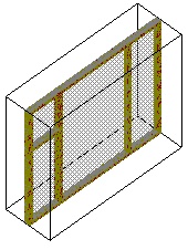
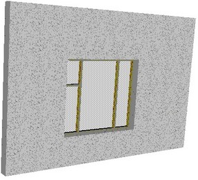
Let’s review an example of automatic creation of a Boolean operation on inserting a fragment. Suppose, there is a 3D model of a building wall, and we need to insert a window in it as a fragment. To do so, let’s create the window model in a special way. Create a tool block as a dummy for cutting the opening in the wall for inserting the window. Then call the “Insertion of 3D Model as Fragment” dialog box (see above). Set the operation type – Subtraction, Use single operation. From the list of operations select the one that created the tool block.
3D Fragment:
Fragment name. This parameter defines the name with which the fragment will be displayed in the assembly’s model tree.
Folder Name. This parameter specifies the name of the folder into which the fragment will be placed in the assembly’s model tree.
Fragment’s name and folder’s name are read from the fragment’s file only upon creation of the new fragment. If the values of these parameters are changed, then upon update of the fragment in the assembly the name and the folder will remain the same.
Copy fragment file to assembly folder. If this parameter is turned on, the file of a fragment that is inserted into the assembly is automatically copied into the folder of the assembly document (or its subfolder). A link to the file that has been copied and not to the original one is written in the properties of the fragment.
You can specify a name for the subfolder to the right of the flag. The subfolder will be created inside the folder of the assembly document into which the file of the fragment will be copied. If this field is empty, the file is copied directly into the folder of assembly.
Default LCS used for Fragment fixing is selected from the list. The list contains all local coordinate systems of the model that have the flag “Use for Fragment insertion” set. When inserting such document as a 3D fragment, the thus defined coordinate system will be automatically offered as the source LCS.
If necessary, the permitted degrees of freedom can be set in the properties of the prepared coordinate system, which will insure the correct behavior of the given 3D fragment in an assembly in the mode of moving mated elements (see the chapter “Mates and degrees of freedom”).
For uncomplicated parts, which can be conveniently inserted into the assembly in the mode of dynamic snapping, the given mode can be turned by default.
Insert 3D fragment on layer. This parameter defines the name of the layer onto which the fragment will be placed upon its insertion into the assembly. If in the fragment’s document the “Insert on layer” parameter is enabled, but upon insertion of the fragment into the assembly this layer does not yet exist, then this layer is created automatically upon request.
Don’t show the message “Fragment doesn’t have bodies”. By default this parameter is disabled. In this case the system does not allow for insertion, into the 3D assembly, of the fragment in which the 3D model is absent or suppressed. The corresponding message in the diagnostics window appears as comments. When this flag is enabled the system allows for insertion of “empty” fragment without issuing any messages.
Set Autosave Parameter. If the given parameter is set up, then upon insertion of the current document as a 3D fragment into the assembly, the “Auto Save” parameter is automatically enabled in the parameters of the fragment. The file of such a fragment will automatically be saved upon each saving of the assembly, with the substitution of the values of external variables and adaptive parameters.
Type of Insertion (for application). The chosen way defines behavior of a 3D fragment at an insert into 3D assembly.
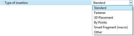
●Standard. Upon insertion into the assembly the translation of the fragment is possible only with the help of the manipulator of LCS (dynamic translation is disabled);
●Fastener. When inserted into the assembly the fragment dynamically moves after the cursor of the mouse;
●3D Placement. This method of insertion is used for quick creation of the arrangement in 3D scene. In the fragment’s file special attachments to the floor, walls, ceiling, horizontal surfaces must be created. These attachments are defined by means of connectors with the specific parameters;
●By points. A fragment can be fixed to the selected in the 3D scene points upon insertion. Its size changes according to the distance between the points.
●Smart fragment (macro). This method of insertion is used for parametric fragments whose insertion scenario is described in the program (macro) stored directly in the file of the given fragment or in the external module (DLL). When inserting the file as a fragment the user-specified macro will be executed.