Chamfers |
  
|
Chamfers |
|
T-FLEX CAD allows creating chamfers and various fillets without any preparatory constructions. The existing elements of the drawing are modified, and new ones created in the process.
Chamfer creation
To create a chamfer, use the command "FE: Create Chamfer". The command is called in one of the following ways:
Icon |
Ribbon |
|---|---|
|
Draw → Draw → Chamfer |
Keyboard |
Textual Menu |
<FE> |
Construct > Chamfer |
To create a chamfer, you need to do several subsequent steps:
1. Select the chamfer type and set its parameters.
2. Select the defining nodes or graphic lines.
Upon calling the command, a dialog box is displayed on the screen for defining the necessary parameters and selecting the type of the chamfer being created. (By default, the dialog box is instantly launched by the system).
Upon confirming the selections with the graphic button [OK], the following actions can be performed:
![]() <P> Set command options
<P> Set command options
![]() <N> Select Node
<N> Select Node
![]() <Space> Select Graphic line
<Space> Select Graphic line
![]() <Esc> Exit command
<Esc> Exit command
T-FLEX CAD supports three main techniques of creating chamfers:
● Chamfer creation by selecting the node through which the hatch contour is passing. The chamfer is displayed in this case as a construction entity.
● Chamfer creation by selecting the node through which two graphic lines are passing. The chamfer is displayed in this case as a graphic entity.
● Chamfer creation by selecting graphic lines. The chamfer is displayed in this case as a graphic entity.
Note that the corner chamfer can be created based on straight graphic lines only.
If the selected elements are not appropriate for the selected chamfer type or were selected incorrectly, then a dialog box is displayed with an appropriate error message.
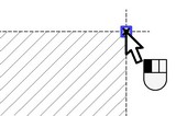
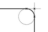
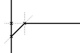
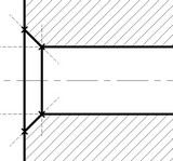
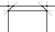
Chamfer creation by a node through which the hatch contour is passing
This technique is intended mainly for creating chamfers at the drafting stage when the graphic lines are not created yet. A chamfer created in this way is drawn as a construction entity. Later, you will have to apply graphic lines over this chamfer manually. On the other hand, if the graphic lines were created before introducing the chamfer, then the chamfer will be displayed as a graphic entity. This technique is intended for constructing only isolated chamfers. Therefore, when constructing chamfers on the surfaces of revolution or two-sided chamfers on the edges of faceted parts, you will have to add the missing construction lines manually.
Remember that this chamfer creation technique works only in the case when the parameter is set among the operation parameters, "Auto change Hatches".
After selecting the type of the chamfer being created and defining the necessary parameters, you need to select the node at which the chamfer will be constructed. This is done by the option ![]() .
.
The selected node must belong to a hatch contour. Upon selecting the node, the chamfer and the construction entities used for its creation are constructed automatically according to the specified parameters.
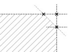
The direction of creating the angular chamfer is determined by the system automatically (depending on where the hatch contour lies).
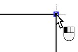
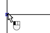
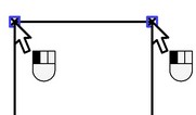
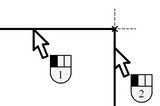
Chamfer creation by the node through which two graphic lines are passing
This technique is used when the graphic lines are already applied on the drawing. A chamfer created in this way is drawn as a graphic entity. All construction entities necessary for the chamfer creation are produced automatically.
When creating a chamfer in this way, make sure that no more than two graphic lines are passing through the selected node. Otherwise, we recommend using another way of chamfer creation, described below.
To create an isolated chamfer, in the operation parameters select the desired chamfer type and set the necessary parameters. After that, specify the node through which two graphic lines are passing.
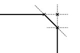
The direction of creating the angular chamfer is determined by the system automatically (depending on where the graphic lines lie).
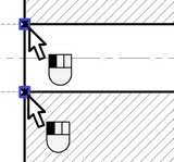
For inner chamfer creation, we recommend using the special chamfer types intended for this purpose. The pointer should be positioned in this case on the desired side of the chamfer creation.
When creating dual chamfers, upon defining the parameters just select two nodes where two respective pairs of graphic lines intersect. The pointer position is of no importance in this case.
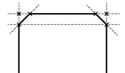
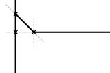
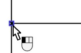
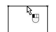
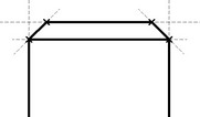
Chamfer creation by graphic lines
This technique, as well as the previous one, is used when the graphic lines are already applied on the drawing. The chamfer created in this way is displayed as a graphic entity. The existing graphic entities are modified, and all necessary construction entities necessary for the chamfer creation are produced automatically in the process.
When creating an isolated chamfer in this way, then, upon selecting the chamfer type and defining the necessary parameters, you need to specify two graphic lines intersecting in one point. The graphic line selection is done by ![]() or by the option:
or by the option:
![]() <Space> Select Graphic line
<Space> Select Graphic line
In this case, the chamfer distance will be counted from the first selected graphic line.


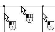
When creating dual chamfers, then, upon defining the necessary parameters, you just need to select their common graphic line lying in between.

In this case, each end point of this line should be connected with exactly one graphic line.
In the ambiguous cases, when more than two lines pass through the end nodes, or the lines intersect without passing through the end nodes, then three graphic lines need to be selected for the dual chamfer creation, in the order starting with the common line of the to chamfers.
 or
or 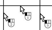
When creating any type of a chamfer, error messages are displayed on the screen in the cases of incorrect element definition.
Chamfer parameters
Since the chamfer parameter definition is the first step of its creation, the default system behavior implies launching the chamfer parameters dialog box immediately upon calling the command. Otherwise, the dialog box is called by the option:
![]() <P> Set command options
<P> Set command options
You can select a predefined type of a chamfer in the "Type" pane of the dialog from the menu of icons.
Radius/Distance. Defines the radius of the inscribed circle in the case of the fillet-type chamfer, or the distance in the case of the corner chamfer.
Angle. This parameter is accessible only when the corner chamfer is selected, and defines the angle of the chamfer being created.
Symmetrical. This parameter is accessible only when making the corner chamfer. Setting this parameter grays out the parameter "Angle", since only the distance is required for defining the symmetrical chamfer.
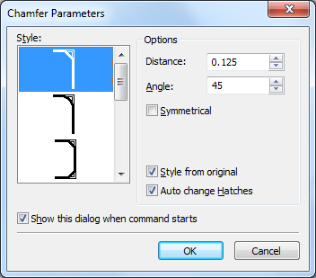
Style from original With this parameter set, the chamfer-making line strokes will have the same parameters as the graphic lines on which the chamfer is based. Otherwise, those strokes will have the parameters currently used by the command "G: Create Graphic Line" or "SK: Create Sketch".
Auto change Hatches. Setting this parameter causes automatic adjustment of the defining hatch to geometry of the chamfer being created. It also makes possible creating a chamfer as a construction element at the node through which the hatch contour is passing.
Show this dialog when command starts. If this parameter is set, this dialog box will be automatically launched upon entering the command. If the parameter is cleared, you will have to call the dialog by the option "Set command options" (the icon ![]() )
)
Editing chamfers
Chamfers are edited as common construction entities.