Creating Custom Lines and Hatches |
  
|
Creating Custom Lines and Hatches |
|
T-FLEX CAD supports creation and use of user-defined custom graphic lines and hatches along with standard types. This chapter describes methods of creating and using those entities.
T-FLEX CAD standard distribution includes several examples of custom lines and hatches that can be used as a sample for creating your own ones.
Graphic Lines
Image of a line is created in general case from several elements described in the line pattern according to the special rules.
Description of a line element constitutes a drawing of the corresponding segment of a line executed with the use of construction lines, nodes, graphic lines, text and hatches. Description of each element of the line must be located on a separate page of the pattern. The sequence order of pages in the pattern’s document is not important.
In general case the image of the line is created from the following elements: “Symbol”, “Space”, “Line”, “Start” and “End”.
Element “Symbol” – “main” element of the line. It can be repeated several times on the line. The number of repetitions is specified in the pattern of the line with the help of the variable CenterMaxCount. If this variable is not created in the pattern, the “Symbol” element is drawn only once on the line. The number of repetitions of the “Symbol” element can be decreased by the system if the number indicated in the pattern can not be fitted to the specified line length. The “Symbol” element is not drawn at all if the variable CenterMaxCount was assigned the value of “0” or if the line length is too small.
“Start” and “End” are the elements that determine the line endings. They are placed at the beginning and the end of the line being created without changes. If in the line pattern the “Start” or “End” elements are absent, it will be possible to specify standard endings for a line on a 2D drawing upon using the given type of a line.
“Space” and “Line” – auxiliary elements of the line that are repeated many times along its length, if required. When creating a line the system draws the “Start” and “End” elements at the line ends, then uniformly places along the line the required number of the elements “Symbol” (as many times as it can be fitted along the line length but no more than it is specified by the CenterMaxCount variable). The remaining intervals between “Symbols” are filled with the “Space” and “Line” elements. Filling in is carried out in the following way: into each interval the maximum possible number of the “Space” elements is inserted. The spaces remaining between them “are covered” automatically by the “Line” elements scaled to the required proportion in such a way that the “Space” and “Line” elements alternate.
Any elements can be absent in the line pattern except the “Space” element.
The required attribute of description of each element of the line is a pair of nodes named in a special way. The nodes determine the points of joining the given element of the line with the neighboring elements (characteristic points). The nodes names are precisely defined for each element of the line:
●The “Symbol” element – specified by nodes CenterStart, CenterEnd;
●The “Space” element – specified by nodes Start, End;
●The “Line” element – specified by nodes LineStart, LineEnd;
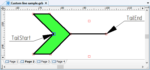
●The “Line start” element – specified by nodes TailStart, TailEnd;
●The “Line end” element – specified by nodes HeadStart, HeadEnd.
Start and end are connected to the main part of the line by TailEnd and HeadEnd nodes, respectively.
When creating a pattern, one can use graphic elements of different color and different width. However, the color and width of a graphic line created from a custom type can be modified only if the whole pattern uses the same color and line width.
The line elements may be of a quite complex shape. When a hatch is created based on graphic lines of a custom type, the hatch contour will not follow the line shape by default; instead, it will be composed of line segments passing through the characteristic points of the line elements. To make the hatch contour exactly follow the line or assume other arbitrary shape, you would need to specify additional 2D paths with special names in the line pattern drawing defining the hatch contour route.
The paths are created separately for each line element. Each path must lie on the same page as the respective line element. The path must start and end at characteristic nodes of its element and be named as one of the following: "Polyline" – the path of the periodical part, "TailPolyline" – the start path, "HeadPolyline" – the end path, and "CenterPolyline" – the path of the center part.
Working with Custom-type Line
To start using a created line type, simply place the line pattern file in the folder …\Program\LinePatterns. Upon restarting T-FLEX CAD, the line types found in this folder will be automatically added to the lists of line types in 2D commands. To delete a custom line type, simply delete the pattern drawing file from …\Program\LinePatterns and restart T-FLEX CAD.
When using a custom line type in a document, the line pattern is saved with that document. Relation with the source file is lost at this point. Therefore, when porting a document file to a computer without the given line type, the image does not get lost.
When porting a document containing custom line types to a computer with existing line type pattern under the same name, the line image stays unchanged in the form of the image saved in the document. To update a line image, you would need to redefine its type over again. To make an update, all you need is to bring up the parameters dialog box for one of the lines and confirm the existing value. New graphic lines of the same type that will be created in this document will take on the current pattern.
Example of Creating Custom Line
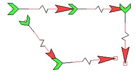
Let's review custom line creation on a simple example. We will create the line pattern shown on the figure. First of all, let's decide on the elements to be included in this line. The figure features: the periodical part – interlaced crosses and segments; center part entered just once – the text "Test"; start and end as special symbols.
![]()
To create the pattern, let's open a new 2D drawing (the command "FN: Create New Model").
Description of each line element shall be placed on a separate page of the document. We will create four pages in the pattern document. For working convenience, each page can be renamed according to its purpose.
To create or rename document pages, use the command "PG: Pages".
When creating descriptor drawings of line types, one can use either use simple sketched lines, or graphic lines snapped to construction lines. For simplicity, we will use free-hand sketching.
We will begin creation of a line pattern from the main element – the periodic part. The descriptor of the periodic part will be the drawing depicting the cross with two strokes, on either side. The points at which this part connects to its neighboring line pieces are marked by the named nodes, "Start" and "End", as shown on the diagram.
A node name is defined by the command "EN: Edit Node", the path name – by the command "EC: Edit Construction".
The lines constituting the periodical part can be of various types, color and width, depending on the desired appearance of the custom line. In this example, the crosses on the line ought to be blue. Therefore, we will make the cross strokes blue, while the lateral strokes - black. Next, we need to decide whether to prescribe the path for hatches. Suppose, this line may be used in the future for creating hatches, so that the hatch or fill lines are not allowed to overlap the cross strokes. For this purpose, we will create a named path, "Polyline", starting and ending in the named nodes "Start" and "End" and passing as shown on the figure.
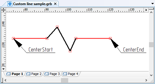
After describing the periodical part, let's proceed to creating the next line element – the center part. To create it, we need to switch to another page of the pattern template.
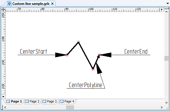
The pattern's center part will include the text "Test" with two strokes on either side. The text can be created by any text entity type (the command "TE: Create Text"). The start and end of the center part are defined by the named nodes "CenterStart" and "CenterEnd". Additionally, we will create a named path "CenterPolyline" for hatches based on this line, as shown on the figure.
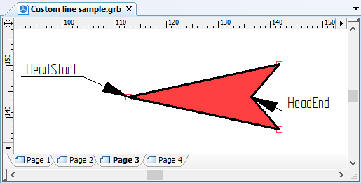
Similarly, we will create description of the tail and head of the line on separate pages, as shown on the figure. We will have to use a hatch to create the filling. No additional paths for hatches will be created. In this case, the contour of a hatch bounded by this line type will follow the lines connecting the border nodes of these line elements.
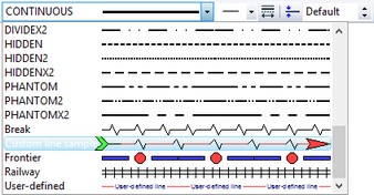
What is left to do before using the created template is to save it in the folder …\Program\ LinePatterns under the name "Custom line sample.grb" and restart T-FLEX CAD. After restarting, the new line with this name will appear in the list of line types. It can be used just like a standard line type.
Hatches
T-FLEX CAD allows creating custom hatch types along with custom graphic line types. To add a custom hatch type to the system, place the file with a hatch pattern in the folder …\Program\HatchPatterns. Upon restarting T-FLEX CAD, the new type will appear in the list of hatches "by pattern". To remove a custom hatch type, simply delete its pattern file from …\Program\HatchPatterns and restart T-FLEX CAD.
Creating Hatch Template
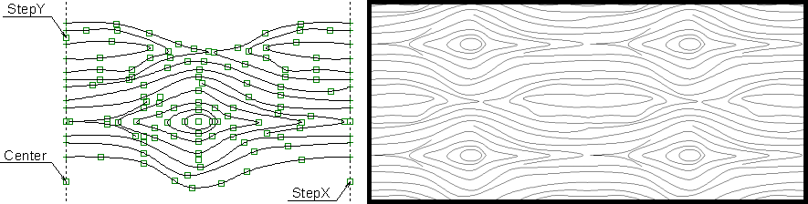
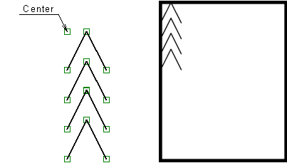
A pattern file is a T-FLEX CAD drawing complying with certain rules. It must contain the image of the hatch pattern composed of nodes, graphic lines, text and hatches, as well as construction elements. The start point of the hatch is defined by a special node named "Center". This node is mandatory in the hatch pattern.
To make a given pattern repeat multiple times when filling the hatch contour, additional named nodes must be defined in the pattern that would define the direction and step of the pattern repetition. The node defining the first hatch direction must be named «StepX»; the node defining the second direction – «StepY». The direction-defining nodes are optional. In the case either of them is not defined, the pattern will be drawn just once in the respective direction.
Working with Custom Hatches
When using a custom hatch type in a document, the hatch pattern is saved with that document. Relation with the source file is lost at this point. Therefore, when porting a document file to a computer without the given hatch type, the image does not get lost.
When porting a document containing custom hatch types to a computer with existing hatch type pattern under the same name, the hatch image stays unchanged in the form of the image saved in the document. To update a hatch image, you would need to redefine its type over again. To make an update, all you need is to bring up the parameters dialog box for one of the hatches and confirm the existing value. New hatches of the same type that will be created in this document will take on the current pattern.
Examples of Creating Simple Hatches
To create a custom hatch pattern, let's open a new document (the command "FN: Create New Model").
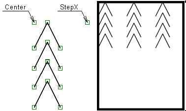
In the opened document, create the image of a hatch pattern as shown on the figure. Make sure to put an additional node on the drawing, named "Center", which must be present on a hatch pattern.
The drawing created in this way can already be identified by the system as a custom hatch template. All that needs to be done is saving the file in the folder …\Program\HatchPatterns (for example, under the name "Custom hatch sample.grb") and restart T-FLEX CAD.
However, since no direction nodes are defined in the pattern, an actual hatch created from this pattern will contain just a single instance of the hatch.
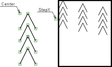
To make the sample defined in the hatch pattern repeat in one direction, you would need to create the respective named node in the pattern, as, for example, "StepX". The position and step of the node will define the step and repetition direction of the pattern sample.
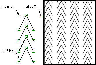
Two named nodes – "StepX" and "StepY" - would allow defining repetition of the pattern sample in both directions. By varying the position of the direction nodes with respect to the "Center" node, one can obtain various hatch appearances all based on the same pattern.
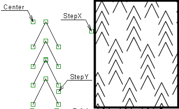
Example of Creating «Woody» Hatch
The custom hatch creation mechanism allows creating even more complex hatches, for example, a "woody" hatch. To create this type of a hatch, a pattern was created as shown on the figure. An appropriately arranged placement of direction nodes yields a hatch imitating wood texture.