Ellipses |
  
|
Ellipses |
|
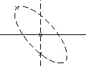
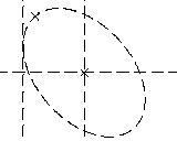
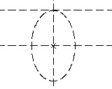
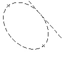
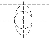
Ellipses in T-FLEX CAD are constructed similar to circles - by defining their geometrical relations with other construction entities. Examples of such relations are the ellipse center being snapped to a node, tangency to a line, tangency to a circle, passing through a node, symmetry with another ellipse. Ellipses, like other construction entities, are displayed in a thin dashed line.
Ellipses in T-FLEX CAD can be divided into two types:
- Ellipses whose size is defined by numerical parameters;
- Ellipses whose position and size are defined by geometrical relations.
Constructing ellipses
To construct an ellipse, use the command "EL: Construct Ellipse". The command can be called by one of the following means:
Icon |
Ribbon |
|---|---|
|
Draw → Construct → Ellipse |
Keyboard |
Textual Menu |
<EL> |
Construct > Ellipse |
T-FLEX supports most common ellipse creation modes, that are:
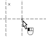
- Constructing an ellipse with the center at a node
- Constructing an ellipse passing through a node
These modes correspond to the following options:
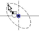
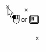
![]() <T> Select Centre Ellipse Node
<T> Select Centre Ellipse Node
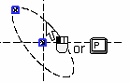
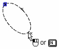
![]() <T> Select Node of Ellipse
<T> Select Node of Ellipse
Upon calling the command, one of the modes activates automatically, as indicated by the pushed icon in the automenu.
Ellipses construction techniques
The following techniques can be used in the mode of constructing ellipses with the center at a node:
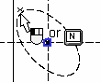
1. Center at node, through node, using parameter
This way of constructing an ellipse is realized in the following sequence of options:
<Enter><Enter><Enter> or <Enter><Enter><P>
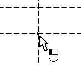
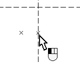
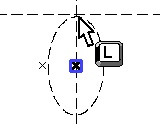
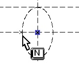
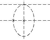
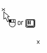
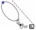
This combination creates an ellipse with the center at a node, with the first semi-axis ending at a node, and the second defined by a parameter. To create this type of ellipse, select the desired node. The node will highlight and an ellipse begin rubberbanding with the center at the selected node. After that, select another node for the ellipse's first semi-axis to pass through. Then move the cursor over desired position and click ![]() or use <P> option.
or use <P> option.


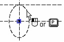
In the latter case, the parameters dialog box will appear on the screen allowing to enter an exact parameter value. If the mouse click ![]() was used for defining the ellipse then the numerical value for the ellipse parameter is derived from the cursor position. The property window can be used for defining the geometrical parameter of the ellipse (the semi-axis length) in transparent mode instead of using the option <P>.
was used for defining the ellipse then the numerical value for the ellipse parameter is derived from the cursor position. The property window can be used for defining the geometrical parameter of the ellipse (the semi-axis length) in transparent mode instead of using the option <P>.
The same way of constructing an ellipse can be realized by the following sequence of options:
<Enter><N><Enter> or <Enter><N><P>
2. Center at node, through two nodes
Upon calling the command, use the following sequence of options:
<Enter><Enter><N> or <Enter><N><N>
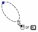
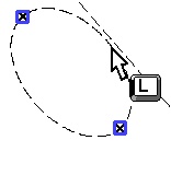
These combinations create an ellipse with the center at a node, the first semi-axis ending at a node, and the second through another node. To create this type of ellipse, select the desired node as the ellipse center. Next, select another node for the ellipse's first semi-axis to pass through. The node can be selected using the option <Enter> or <N>. Then move the cursor over the node defining the position of the second semi-axis and type <N>. The required ellipse will be created.

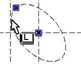
3. Ellipse with the center at a node, passing through node, tangent to line
Upon calling the command, use the following sequence of options
<Enter><Enter><L> or <Enter><N><L>
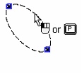
These option combinations create an ellipse with the center at a node, the first semi-axis ending at a node and the second semi-axis defined by tangency to line. To create this type of ellipse, select the desired node as the ellipse center, then use the option <Enter> or <N> and select another node for the ellipse's first semi-axis to pass through. Then move the cursor over the line to be making tangency with the ellipse and type <L>. The required ellipse will be created.
4. Ellipse with the center at a node, tangent to line, using parameter
Upon calling the command, use the following sequence of options:
<Enter><L><Enter> or <Enter><L><P>
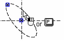
These option combinations create an ellipse with the first semi-axis defined by tangency to a line at the tip of the semi-axis and the second semi-axis driven by the parameter. To create this type of ellipse, first select the desired node as the ellipse center. Next, use the <L> option and select the line making tangency with the ellipse at the tip of the semi-axis. Then move the cursor over desired position and click ![]() . The exact value of the second semi-axis length can be entered in the property window in transparent mode or in the parameters dialog box (the option <P>). The required ellipse will be created.
. The exact value of the second semi-axis length can be entered in the property window in transparent mode or in the parameters dialog box (the option <P>). The required ellipse will be created.

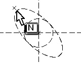
5. Ellipse with the center at a node, tangent to line, passing through node
Upon calling the command, use the following sequence of options:
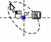
<Enter><L><N>
This combination of options creates an ellipse with the first semi-axis defined by tangency to a line at the tip of the semi-axis and the second semi-axis ending at another node. To create this type of ellipse, first select the desired node as the ellipse center, and then select the line making tangency with the ellipse at the tip of the semi-axis. After that, select a node to define the position of the ellipse's second semi-axis. The required ellipse will be created.
The following techniques can be used in the mode of constructing ellipses passing through a node:
1. Ellipse passing through two nodes, using parameter
Upon calling the command, use the following sequence of options:
<Enter><Enter><Enter> or <Enter><Enter><P>
or <N><N><Enter> or <N><N><P>
These combinations create an ellipse, passing through two nodes, with the second semi-axis defined by a parameter. To create this type of ellipse, move the cursor over the first node and press the option <Enter> or <N>. Next, with the same options select the second node. Then move the cursor over desired position and click ![]() . To enter the exact value of the second semi-axis length, use the property window or the parameters dialog box (the option <P>). The required ellipse will be created.
. To enter the exact value of the second semi-axis length, use the property window or the parameters dialog box (the option <P>). The required ellipse will be created.
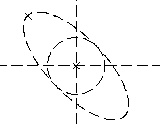
2. Ellipse passing through three nodes
Upon calling the command, use the following sequence of options:
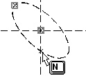
<Enter><Enter><N> or <N><N><N>
These option combinations create an ellipse passing through two nodes, with the second semi-axis defined by the condition of passing through the third node. To create this type of ellipse, select three nodes using the <N> option (the first and second nodes can also be selected by the option <Enter>).
3. Ellipse passing through two nodes, tangent to line
Upon calling the command, use the following sequence of options:
<Enter><Enter><L> or <N><N><L>
These option combinations create an ellipse, passing through two nodes, with the second semi-axis defined by tangency to the line at the tip of the semi-axis. To create this type of ellipse, use the option <Enter> or <N> and select the first node, then, using the same options, select the second node. After that, move the cursor over the line that will be making tangency with the ellipse at the tip of the second semi-axis. The required ellipse will be created.

Another two types of ellipses can be constructed in any ellipse creation mode:
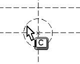
1. Ellipse tangent to a circle, passing through node
Upon calling the command, use the following sequence of options:
<C><N>
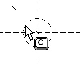
This set of options creates an ellipse with the first semi-axis defined by the radius of a circle concentric with the ellipse. The second semi-axis is defined by selecting its end node. To create this type of ellipse, select an existing circle using <C> option, and then move the cursor over the node to become the end of the second semi-axis, and type <N>. The required ellipse will be created.
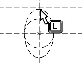
2. Ellipse, tangent to a circle and a line
Upon calling the command, use the following sequence of options:
<C><L>
This set of options creates an ellipse with the first semi-axis defined by the radius of a circle concentric with the ellipse. The second semi-axis defined by tangency to a line. To create this type of ellipse, select an existing circle using <C> option, and then move the cursor over the line to define tangency to the ellipse, and type <L>. The required ellipse will be created.
When creating ellipses by any of the above means, you can select elements using the following icons:
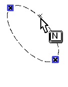
![]() <N> Select Node
<N> Select Node
![]() <C> Select tangent Circle
<C> Select tangent Circle
![]() <L> Select tangent Line
<L> Select tangent Line
![]() <A> Select axis of symmetry (straight Line)
<A> Select axis of symmetry (straight Line)
Object snapping mode can be used as well.
Ellipses created from 2D projection, 2D fragment or copy
Such ellipses can be created in object snapping mode, provided that the appropriate parameter is set on the "Snap" tab of the command "SO: Set System Options". Move the cursor over a graphic entity – full ellipse or elliptic arc that is part of a 2D projection, 2D fragment or copy. The line will highlight. Click ![]() . An ellipse will be created on top of the selected entity.
. An ellipse will be created on top of the selected entity.
If the object-snapping mode is off, then only 2D projection entities can be used for creating an ellipse. This is done by selecting the desired projection on the drawing using the ![]() option. The selected projection will highlight and the cursor will gain a glyph
option. The selected projection will highlight and the cursor will gain a glyph ![]() . To create a construction line now, simply point the cursor to a projection entity – ellipse or elliptic arc and click
. To create a construction line now, simply point the cursor to a projection entity – ellipse or elliptic arc and click ![]() .
.
The following options will become available in the automenu:
![]() <P> Set ellipse parameters
<P> Set ellipse parameters
![]() <Esc> Cancel selection
<Esc> Cancel selection
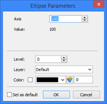
Ellipse parameters
When creating or editing ellipses, one can control various parameters. The geometrical parameter (the semi-axis length) can be defined in transparent mode using the property window. The general system parameters are controlled via the complete ellipse parameters dialog box via the option:
![]() <P> Set ellipse parameters
<P> Set ellipse parameters
Axis. The length of one of the ellipse's semi-axes. The input can be a number, a variable or an expression.
Value. Displays the numerical value of the "Axis" parameter. Level. Places the ellipse on a certain visibility level.
Layer. The name of the layer the ellipse belongs to.
Set as default. Setting this flag means, the current dialog box settings will be used as the defaults for ellipses creation in future.
Editing ellipses
Editing ellipses, just like any other construction entities is done via the command "EC: Edit Construction".
Icon |
Ribbon |
|---|---|
|
Draw → Additional → 2D Construction |
Keyboard |
Textual Menu |
<EC> |
Edit > 2D Construction |
This command allows changing ellipse parameters, assigning a name to an ellipse and deleting it.
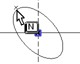
An ellipse can be selected by pointing at with the cursor and clicking ![]() or via the option:
or via the option:
![]() <E> Select Ellipse
<E> Select Ellipse
The ellipse editing command, "EC: Edit Construction", can also be accessed from within the command "EL: Construct Ellipse" via the option:
![]() <F4> Execute Edit Construction command
<F4> Execute Edit Construction command