Getting Started |
  
|
Getting Started |
|
This chapter contains sections helpful in getting started with the system setup and basic operation: "System Requirements", "T-FLEX CAD System Setup", "Basic Terms and Drawing Techniques", "Quick Reference on User Interface".
System Requirements
Hardware Requirements
Software Requirements |
Windows XP (Service Pack 3), Windows Vista, Windows 7, Windows 8/ Windows 10 |
Minimum Processor: Recommended Processor: |
32-bit or 64-bit Intel or AMD processor with SSE2 support Core i7 processor or equivalent |
Videocard:
Recommended videocard: |
Videocard with OpenGL 3.3 support is recommended for efficient work with assemblies. OpenGL 4.2 – for improved visualization of models in 3D scene. OpenGL 1.0 allows to work with 3D models, but with restrictions (threads, welds, graphic sections and textures will not display). Videocard supporting CUDA 2.3 or higher is required for creation of photorealistic images with NVIDIA Optix technology.
High-performance NVIDIA videocard with 1GB of memory or higher and with Open GL 4.2 support or higher. |
Minimum RAM: |
1 G |
Recommended RAM: |
4G and more* (for very large assemblies) |
* 32-bit operating systems Microsoft Windows have a limitation of 4GB of memory address space. This 4GB space is evenly divided into two parts, with 2GB dedicated for kernel usage, and 2GB left for application usage. Each application (including T-FLEX CAD) gets its own 2GB, but all applications have to share the same 2GB kernel space. For Windows XP and Windows Vista it is possible to increase the default allocation capabilities up to 3GB (3GB for user mode, 1GB reserved for kernel). Such capability requires additional tunings in order to be effective (see http://support.microsoft.com for more information).
64-bit operating system Windows does not have limitations in terms of size of random access memory and does not require any additional settings to control it. Up to 4GB of memory is automatically allocated for 32-bit applications (such as T-FLEX CAD).
To fully exploit the capabilities of 64-bit operating system, there is a special 64-bit version T-FLEX CAD x64. Combination of T-FLEX CAD x64 with Windows x64 allows using unlimited amount of random access memory in working with T-FLEX CAD.
T-FLEX CAD System Setup
Protection keys
Security keys created by the Sentinel HASP technology serve to protect T-FLEX CAD from unauthorized usage. There are two types of protection keys: hardware and software.
The hardware protection key is recorded on a physical device that is inserted into a USB port on the computer. The key has its own memory, which contains information about the available user licenses.
Software protection key is a program and does not require a physical device. It is associated with a specific computer.
The hardware and the software key may be network or local.
Local software protection key is installed on single computer and cannot be used on another one.
Local hardware protection key allows you to work on any computer that is connected to the physical device with the recorded key.
If you are using a network security key of any type, the network administrator is granted access to manage available licenses and information about these licenses. Access to the network key license management is allowed through the program Sentinel Admin Control Center.
Software for the protection key is installed automatically as part of the T-FLEX CAD installation process.
Installing Software and Hardware Protection Key
If you use a hardware protection key do not insert it into USB-port until T-FLEX CAD installation complete.
T-FLEX CAD installation with examples, libraries and auxiliary utilities is available on DVD.
Perform the following steps to install T-FLEX CAD on your PC:
1. Insert DVD-disk with T-FLEX CAD installation into DVD-drive.
2. Run Setup.exe file from T-FLEX Prerequisites folder.
This installation should be performed one time even after T-FLEX CAD reinstalling or uninstalling.
3. Run T-FLEX CAD.msi from “T-FLEX CAD” folder and follow installation wizard instructions.
You can install either T-FLEX CAD x32 or T-FLEX CAD x64 running msi file from appropriate folder.
Installation wizard will install examples and standard parts automatically.
4. Run appropriate msi files to install tutorials and necessary add-ons.
Press [Cancel ] button to interrupt installation process.
After installation complete new folder will be created in Program Files directory on your PC.
What is going on in setup?
The T-FLEX CAD application files on the CD ROM are in a compressed format. The installer extracts and copies these files into the specified folder on your PC's hard disk. The memory and disk space are monitored during the installation, and an error message is displayed if these are insufficient.
T-FLEX CAD is distributed with a set of sample drawings, and a library of standard elements. The installer program creates appropriate subfolders under the installation home folder. The data structure of these subfolders is as follows:
\T-FLEX Parametric CAD\ |
|
|
|
PROGRAM |
The T-FLEX CAD system files |
|
Libraries |
The library element files |
|
Documents |
The system reference files |
|
API |
Examples on Open API and Application Wizard usage for developing T‑FLEX CAD add-on applications. |
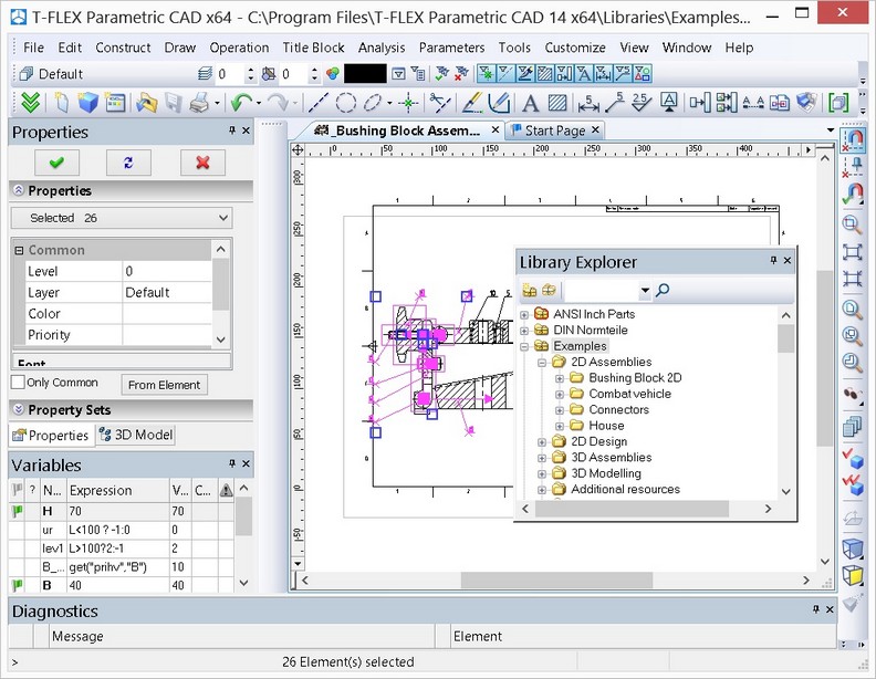
The T-FLEX CAD Main Window Layout
After launching of T-FLEX CAD the dialog box “Start Page” opens up. It includes several sections. In the section Recent Documents a list of recently used documents is shown. To open any of these documents, it is sufficient to point the cursor at any of them and press ![]() . The button [Open…] can also be used.
. The button [Open…] can also be used.
The section Create New Document allows creating a new document on the basis of any of the existing templates. For convenience all templates are divided into groups (“Common”, “Bom”, “Ray Tracing”).
The content of these sections duplicates the functionality of the menu File > Recent Files and the command FP: Create New Document Based on Prototype. More details on how to use these capabilities will be given in the chapter “Main Concepts of System Operation”.
The chapter What’s new contains information about the installed version.
When you select Resources tab, tflexcad.ru page opens in the browser. Here you can download the sample files, libraries, etc.
The chapter Tutorial contains basic information about T-FLEX CAD. The information is useful for novice users.

The dialog box “Start Page” is always visible on the screen when the standard settings of the system are used. Its tab will be aligned with the tabs of the open documents of the system (see below).
The window can be controlled by the Customize > Tool Windows > Start Page item.
In ribbon interface, you need to choose a special icon in the top right part of the window.

Control of the displaying of the dialog box Start Page during all sessions can be carried out through the dialog box of the command SO: Set Systems Options parameter Show Welcome Page at Start on the tab Startup.
Interface
There are two interfaces in T-FLEX CAD: ribbon and textual. Ribbon interface offers a convenience of commands usage and their easy searching. Textual interface was used in previous versions of the system.
You can use flag Ribbon mode in the Customize system command on the Options tab.

Ribbon
All commands on ribbon are distributed on tabs. Name of each tab reflects the content. Commands icons are grouped.

The Quick Access Toolbar containing main commands for document management is located in the header of the window. The commands are: 2D Drawing, Assembly drawing, 3D Model, 3D Assembly, Open, Save, Undo, Redo. These commands are always available and do not depend on the active tab. The Set Document Parameters command ![]() is also located here.
is also located here.

The File ![]() button contains commands for operating with the document.
button contains commands for operating with the document.

Text menu, which contains the full set of commands, can be accessed by clicking on the ![]() button.
button.
In the upper right corner you may find: a field for displaying of integration with T-FLEX DOCs ![]() , a drop-down menu of help information
, a drop-down menu of help information ![]() , a drop-down menu of system settings
, a drop-down menu of system settings ![]() , a command for the start page displaying
, a command for the start page displaying ![]() , a command for the full screen mode activation
, a command for the full screen mode activation ![]() .
.

In the ![]() drop-down menu you can specify displaying of the tabs.
drop-down menu you can specify displaying of the tabs.
A help drop-down menu ![]() contains commands for invoking help information about the system.
contains commands for invoking help information about the system.


The customize drop-down menu ![]() contains commands for changing various system settings.
contains commands for changing various system settings.
Ribbon adapts to the current mode. For example, when switching between 2D and 3D views, tabs are also switching between Draw tab and 3D Model tab.
Ribbon remembers the tab where the last selected command was located. If you choose a command from "Measure" tab in 3D view, and then continue operating in 2D view, the next activation of the 3D view will re-enable tab "Measure".
You can hide Ribbon by double-click on any tab to release a work space. Ribbon appears again in case of any of its tabs choice. It is possible to recover Ribbon by double-clicking on any of its tabs.

Tabs can be switched by means of a mouse wheel if you put a cursor at them and rotate a wheel.

If some equivalent commands in Ribbon are united in a drop-down list, the last chosen command is remembered and displayed in Ribbon.

For personal setup it is possible to edit the existing tabs and to create your own tabs with necessary commands and operations.
Textual interface

Main Menu contains the textual menu of the T-FLEX CAD commands by groups.
Main Toolbar contains icon buttons for T-FLEX CAD commands. Besides the main toolbar, the application window of the system can contain several toolbars (including the toolbars created by the user). Toolbars can be docked along one of the main window borders, or stand alone as floating windows.
System Toolbar contains the fields for modifying current settings of entities, such as color, line type, level, and layer. Also contains controls for modifying layer configuration, level configuration of the current document, and selector settings.
Elements of T-FLEX CAD Control

Elements of Control
Ruler indicates current X and Y coordinates in the active drawing.
The active drawing window - the graphics window for displaying the drawing. Drawings can only be created and edited in this window.
Automenu - a menu of icon buttons for the options available within the current command. If no command is current, the automenu is empty.
Status bar contains the name of the current command, a prompt for the expected user action, the current X and Y coordinates, and the command-dependent auxiliary coordinate.
Pages Tabs provide quick access to the desired page in a multi-page document. To activate a page, select the respective tab. Tabs are not shown for the hidden pages.
Documents Tabs help quick navigation through the open documents. To activate a document, select the respective tab.
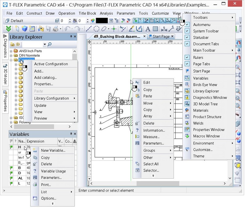
The user can reconfigure the layout (position and visibility) of the dialog boxes and various control bars on the main T-FLEX CAD window. Use the menu Customize > Tool Windows or Customize > Customize…”.
Service Windows
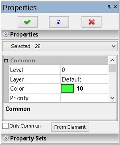
Properties Window
|
Is used for specifying parameters in transparent mode within most 2D and 3D commands. This window can be docked along one of the main window borders, or float. |
Bird’s Eye View Window
|
Displays the fitted view of the drawing, regardless of the current pan/zoom in the drawing window. Helps to quickly pan to any portion of the drawing. The window can be docked along one of the main window borders, or float. |
Library Explorer Window
|
Contains graphical and textual representation of the libraries and the drawings in the current library configuration. Helps quick loading of a desired drawing and browsing drawing libraries. The window can be docked along one of the main window borders, or float. |
3D Model (only for 3D release)
|
This window displays the structure of the 3D model, such as the existing workplanes and other auxiliary 3D entities and their dependencies, and the operations used for creating the model. The window can be docked along one of the main window borders, or float. |
Diagnostics Window
|
Displays messages about errors or failures that may occur during T-FLEX CAD operation. The window can be docked along one of the main window borders, or float. |
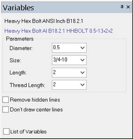
Variables Window
|
An additional window of variables editor which enables to work with the variables in an transparent mode, and simultaneously work with the drawing window or 3D model window. Upon changing the value of the variable, the model is regenerated transparently in the current window. All changes are immediately reflected on the drawing. This window can be docked along one of the main window borders, or float. |
Macros Window
|
This window displays macros of the current document and macros from T-FLEX installation folder “…\Program\ Macros”. The window helps to start macros for execution. |
Materials Window
|
Window for working with the materials of 3D model and also with the material libraries of T-FLEX CAD. |
Model Elements Window
|
All created in document elements are shown in the Model Elements window. Context menu is available for each of them. |
External Links Window
|
External Links window allows to manage existing files links used in the current document. |
Window “Product’s structure” |
Displays the model’s structure. It allows us to add annotation elements to the product’s structure, transforming it to the form of a single or group bill of materials. |
Studies Window (only for 3D release) |
The window displays data of the current document FEA and Dynamics studies. This window can be used for operations with studies. |
Weld Window |
This window contains lists of welds created in the current document. |
Structural Elements Window |
Used for existing structural elements displaying. |
Working with tool windows
The system tool windows (the properties window, "3D model", "Library Explorer", the Bird's eye view window, "Macros", the diagnostics window and other windows) can be positioned in the main application window in various ways. Those can be "docked" at the side of the working window, made "hideable" or set to "floating" mode. To save the workspace, some windows can be joined in one group window. Unused tool window can be turned off.
To engage a tool window, use the menu "Customize|Tool Windows". The same dialog can be accessed by right clicking ![]() over an automenu of any other toolbar. Windows are closed by the button
over an automenu of any other toolbar. Windows are closed by the button ![]() located on the title bar of the tool window.
located on the title bar of the tool window.
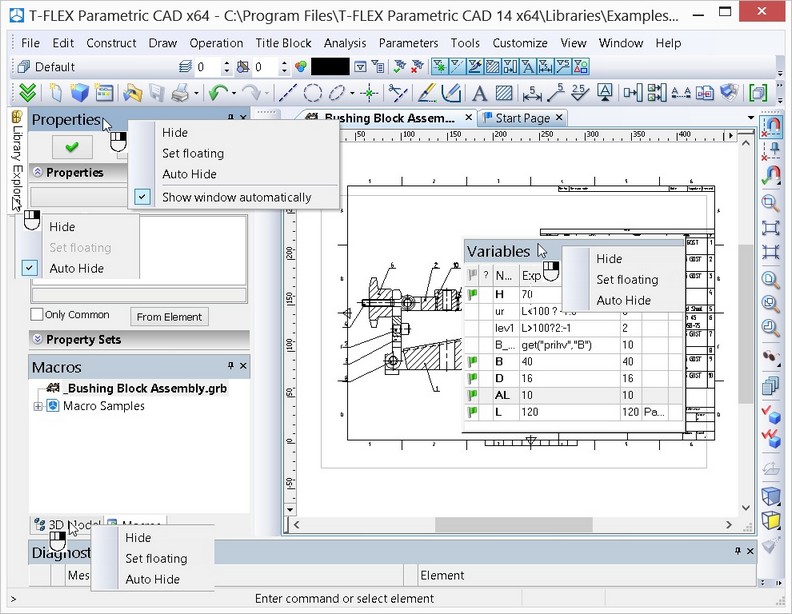
In controlling the service windows, the context menu accessed by clicking ![]() on the heading or the tab of the window can be used. The menu has several commands for controlling the state of the window:
on the heading or the tab of the window can be used. The menu has several commands for controlling the state of the window:
●Hide. Remove the window from the screen;
●Set floating. Turn on the “floating” mode for the window (see below);
●Auto Hide. Turn on/off the auto hide mode for the window.
A set of commands available in the context menu is dependent on the state of the current window.
Upon the first launch of the system, the "3D Model", "Library Explorer" and "Properties" windows are already present in the application workspace. Those are placed in the "docked" mode along the left border of the workspace and are joined in one group window. If necessary, the two windows can be moved to any location along the perimeter of the application workspace. To display one of the joined windows separately, grab that window at its tab by pressing ![]() and "drag" to the desired position.
and "drag" to the desired position.
To add a tool window to an already existing or a new group window, grab the intended window by pressing ![]() and dragged to the title area of the other window or to the tabs area of an already existing group window. Upon dragging the windows several prompt signs will emerge showing where the window will be placed when the mouse is released.
and dragged to the title area of the other window or to the tabs area of an already existing group window. Upon dragging the windows several prompt signs will emerge showing where the window will be placed when the mouse is released.
In the cases when most of the workspace is needed, you can set the "auto hide" mode for the tool windows.
In the auto hide mode, the window will appear as a tab located along the perimeter of the main application window. The window will appear automatically as you point the mouse to this tab. Once the pointer leaves the window area, it will automatically collapse.
To turn on the auto hide mode for the window, the context menu “Auto Hide” accessed by clicking ![]() on the header or the tab of the window can be used. Moreover, when the service window is in fixed position on one side from the main window of the program, the button
on the header or the tab of the window can be used. Moreover, when the service window is in fixed position on one side from the main window of the program, the button ![]() appears on the header of the window. Pressing this button also turns on the auto hide mode for the window.
appears on the header of the window. Pressing this button also turns on the auto hide mode for the window.
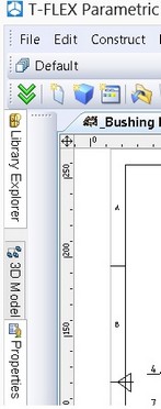
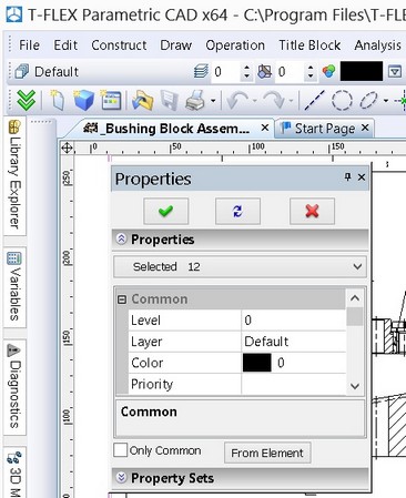
"Properties" window tab in the autohide mode
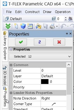
"Properties" window expands when pointed by mouse
The auto hide mode can be canceled by right clicking ![]() on the window tab and clearing the flag of the "Auto hide" parameter. This mode helps save significant space on the screen while maintaining benefits of the tool window functionality. Also, to turn off the auto hide mode, the button
on the window tab and clearing the flag of the "Auto hide" parameter. This mode helps save significant space on the screen while maintaining benefits of the tool window functionality. Also, to turn off the auto hide mode, the button ![]() on the header of the window can be used.
on the header of the window can be used.
It is often convenient to set some of the tool windows or a whole group window into the "Floating" mode. In this way, the tool window can be placed anywhere within the application workspace without being docked.
Setting a tool window into the floating mode is done by grabbing the window title or tab in the group window by pressing ![]() and dragging into the drawing area of the application window. You can set to this mode not only separate windows, but group windows as well. To do this, grab a group window at the title by pressing
and dragging into the drawing area of the application window. You can set to this mode not only separate windows, but group windows as well. To do this, grab a group window at the title by pressing ![]() drag into the drawing area of the application window in the same way.
drag into the drawing area of the application window in the same way.
To turn on the floating mode for a window the command “Set floating” in the context menu of the given window can be used. Note that if a window, for which the context menu is called, was grouped with other service windows into a group window, then the floating mode will be applied to the whole group window.
To cancel the floating mode, grab the window at the title and by pressing ![]() drag it to a side of the drawing window. As you do this, the outline of the dragged window will be changing depending on available snapping: separately (right, left, bottom, etc.) or in a group window. To suppress snapping to sides, while moving the window hold <Ctrl> the key.
drag it to a side of the drawing window. As you do this, the outline of the dragged window will be changing depending on available snapping: separately (right, left, bottom, etc.) or in a group window. To suppress snapping to sides, while moving the window hold <Ctrl> the key.
Working with Multiple Monitors
You can open multiple windows for one document and operate with it on multiple monitors.
For example, if your computer is connected with two monitors, you can display 3D model on one of them and a drawing with the same model projections on the other. Changes in the model are displayed in all main windows that are associated with the same document. So that, changes in the model made on the first monitor are immediately displayed on the projections at another monitor after the Shift+f7: Regenerate all command activation.

New main windows are independent of each other. Each of the windows has commands, input parameters, and other user interface elements.
The system will ask you about saving of the document only when you close the main window with its last open copy.
You can copy document to a new main window via command New Main Window:
Icon |
Ribbon |
|---|---|
|
View → Window → New Main Window |
Keyboard |
Textual Menu |
|
Window > New Main Window |
You can transfer document to a new main window via command Move to Main Window:
Icon |
Ribbon |
|---|---|
|
View → Window → Move to Main Window |
Keyboard |
Textual Menu |
|
Window > Move to Main Window |
The commands are also available in the document tabs context menus.

Before new main window opening, you can specify the Views placement for it.

The main windows related to a single document are numbered. Number of a window is displayed in its title in parentheses. It helps to choose the window if you want to copy or transfer a document.
![]()
Drawing Basic Terms
Drawing in T-FLEX CAD involves using several types of entities.
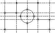
Construction entities. These make the framework of a drawing. The graphic entities of the actual drawing are drawn over the construction entities. The construction entities include construction lines and nodes. These construction lines and nodes are the principal elements for defining the parametric layout of the drawing. The analog for these in the conventional drawing is the thin pencil lines to be later marked in ink. The parametric behavior of the drawing will be driven by the relationships between the various-type construction lines and the nodes. This will result in a particular way in which the drawing geometry will adjust to changing parameters. The construction entities are displayed solely for user reference. They do not appear on printouts or plots, and are not exported.
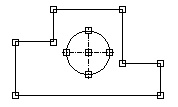
Graphic Entities. These constitute the actual drawing of the drawing. The graphic entities include the graphic lines, dimensions, text, hatches, GD&T symbols, etc. These entities may be "snapped" to respective construction entities. In this case, modifications in the construction entities and nodes propagate on the corresponding graphic entities. This is the main technique for parametric design in T-FLEX CAD. The graphic entities constitute the drawing image on a printout or a plot.
The Auxiliary Entities of T-FLEX CAD are variables, databases, reports and other certain system data.
Construction Entities
Construction Lines are the core elements of the T-FLEX CAD parametric model. These are "thin" base lines that define the parametric framework of a drawing. The construction lines include infinite straight lines, circles, ellipses, splines, offset lines, function curves, and paths. They are displayed as dashed lines. The in-depth description of the construction line types and their creation techniques is given in the following chapters. The particular ways of creating construction lines define the behavior of the drawing as the user modifies location of any construction line. This is due to interdependencies among the construction lines that are established at their creation.
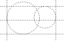
A Node is a point whose placement is defined by a particular way of creation and by interdependencies with other entities in the model. Nodes are also the core elements of the T-FLEX CAD parametric model. Typically, nodes are created at construction line intersections.
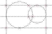
The nodes are directly involved in defining the parametric model that will drive other construction entities. Examples of such situations are: a line passing through a node at a specified angle to another line, a circle passing through two nodes, etc. Modifying the location of one of the lines defining the node will cause the node to adjust. This change will propagate on other construction entities related to the node. The nodes are also used for defining the ends of the graphic line segments and other graphic entities.
Besides the nodes that are defined by intersections of pairs of construction lines, T-FLEX CAD supports several other types of nodes whose creation techniques are described below. For now, let's consider only the difference between the "snapped" and "free" nodes.
The typical technique of creating a parametric model implies creating nodes at construction line intersections. This technique is called "constrained drawing mode". While in "constrained drawing" mode, creating a node at some location will undergo automatic snapping to the nearest to cursor pair of construction lines and their intersection.
Creating "free" nodes is a special drawing technique used in non-parametric drawing, such as sketching. This will further be referred to as "free drawing mode". While in "free drawing" mode, the nodes are created exactly under the cursor, without snapping to construction line intersections.
The "constrained drawing" mode is indicated by the icon ![]() of the T-FLEX CAD automenu.
of the T-FLEX CAD automenu.
The "free drawing" mode is indicated by the icon ![]() of the automenu. Switching between these modes is done with <Ctrl><F> or by picking the respective automenu icon.
of the automenu. Switching between these modes is done with <Ctrl><F> or by picking the respective automenu icon.
The recommended drawing technique is using the "constrained drawing" mode. Avoid using mixed modes on the same drawing, as this may cause errors in parametric modifications of the drawing.
Fixing Vector is a construction entity that helps defining the location and orientation of the drawing that is used as a fragment in an assembly drawing. |
|
Connector is a construction entity that provides a placement reference for 2D fragments. Besides the geometrical location (the origin of the coordinate system and the axes orientation), a connector can keep additional data (both the dimensional and non-dimensional) that is necessary for "plugging in" the 2D fragments. These data are stored as a list of named values that can be either fixed constants or modifiable parameters. As for the parameters, their names within the connector are significant in the following way: assigning same names to the external parameters of the element to be connected makes these parameters assume the values of their counterparts in the connector. |
|
Graphic Entities
Graphic Lines are the lines constituting the actual drawing of the drawing. Graphic lines include straight segments bound by a pair of nodes, full entities, such as circles, closed splines and so on, except for the infinite straight lines, and the portions thereof bound by pairs of nodes, also splines through nodes. The graphic lines may be of various types (main solid, thin solid, dashed, dotted etc. They are snapped to nodes and construction lines. |
|
Hatches and Fillings are closed-contour single-connected or multiple-connected areas filled with various patterns or colors. Hatch contours are snapped to nodes and construction lines. They adjust to node location modifications. The filling pattern also regenerates automatically as the contour changes. |
|
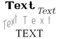
Text is a single-line or multi-line textual data input via a text editor or directly in the drawing window. Either way of input supports various fonts. Besides, T-FLEX CAD supports use of paragraph formatting and other operations. A text can either be located in absolute coordinates and thus independently from the construction entities, or be snapped to construction lines and nodes. |
|
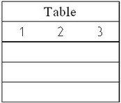
Table is an element of drawing layout. It is composed of lines and textual data. Tables are created by the same command as text. A table can either be located in absolute coordinates and thus independently from the construction entities, or be snapped to nodes. |
|
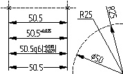
Dimension is a standard element of drawing layout. It is composed of lines and textual data. A dimension is created with respect to construction lines and nodes. T-FLEX CAD supports several dimensioning standards, including ANSI and Architectural ANSI. Dimensions automatically adjust to parametric modifications of the drawing. |
|
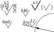
Roughness Symbol is a standard element of drawing layout. It is composed of lines and textual data. A roughness symbol can either be located in absolute coordinates, or be snapped to a node, construction or graphic line, and to a dimension. |
|
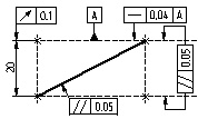
Geometric Datum and Tolerance Symbol (GD&T Symbol) is a standard element of drawing layout. It is composed of lines and textual data. A GD&T symbol can be snapped to a node, construction or graphic line, and a dimension, or located in absolute coordinates. |
|
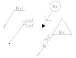
Leader Note is a standard element of drawing layout. It is composed of lines and textual data. A leader note can either be located in absolute coordinates, or snapped to a node, construction or graphic line. |
|
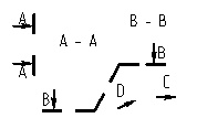
Section symbol is a standard element of drawing layout. It is composed of lines and textual data. This symbol marks various views, sections and cuts. The element can either be located in absolute coordinates, or snapped to a node. |
|
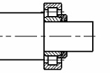
Fragments are T-FLEX CAD drawings that are used in other drawings in subassemblies and assemblies. Any T-FLEX CAD drawing can be used as a fragment. A parametric fragment in T-FLEX CAD is a drawing that can be inserted (assembled) into another drawing to a specified location and with modified parameters. The fragment appearance shall change to satisfy the parameter values. In order to create parametric fragments, the user needs to follow certain rules described below. |
|
Pictures are graphic images saved in various file formats. |
|
Copy is an element duplicating the original, except for the different transformation parameters. |
|
Controls are special elements in T-FLEX CAD used for creating user-defined dialog boxes customized for controlling external parameters of a parametric model. |
|
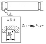
Drawing View is a T-FLEX CAD entity that displays the content of one drawing page on another page, appropriately scaled. This is a rectangular area of specified size that will contain the other page image. The main purpose of this element is combining in one drawing several elements of different scale. A common use of the Drawing View is for creating enlarged detail views. |
|
Auxiliary Elements
Variable is a system element for specifying non-geometrical dependencies between the various parameters. One main use of the variables is assigning their values to the construction line parameters. Consider, for example, a line parallel to a given line, at a certain distance. This distance can be defined not only by value, but via a variable as well.
Database is a table of information ordered in a certain way. Databases are used for storing information required in the drawing.
Reports are textual documents that are created with the T-FLEX CAD text editor. Reports can include the system variables and are used for creating various text documents.
Drawing Techniques
A T-FLEX CAD drawing can be created in one of the following ways:
Parametric Drawing. This is the recommended drawing technique in T-FLEX CAD. Take the advantage of parametric design capabilities of T-FLEX CAD to create a drawing that can be easily modified according to your design intent. Such a drawing can also be added to a parametric model library to be later used in other, more complex drawings. In the latter case, one can specify a new location for the drawing as a fragment, and modify parameters to obtain a desired shape.
Non-parametric Drawing (Sketch). This is a conventional drawing similar to those created by most CAD systems. This drawing is created by using the standard set of functions for plotting different basic entities (straight lines, arcs, circles, ellipses, splines etc.) and by using the mechanism of objects snaps. These drawings do not have advantages of parametric drawings as far as efficient modification of parameters (dimensions) is concerned, however, in certain cases creating these drawings saves time and can give the benefit when significant subsequent modification is not required.
Creating Parametric Drawing in T-FLEX CAD
Creating a drawing in T-FLEX CAD begins with creating construction entities. Construction entities can be created by various means. First, create the base construction lines that will be used as a reference for additional construction lines. The base lines can be vertical or horizontal. Next, create straight lines and circles dependent on the base lines. For instance, construct parallel lines, tangent circles, etc. The way in which additional lines are created is stored in the model. The line intersections provide reference locations for nodes that need to be created for further construction.
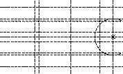
More straight lines and circles can then be created referencing the earlier ones in various ways. A line, for instance, can be created through two nodes; a circle can be drawn through a node and tangent to a line. All these construction steps are stored, and in future the thus created entities will be adjusting to the base and other entity modifications according to their creation history.
Thus, the early stage of creating a drawing involves building parametric dependencies among construction entities that become the parametric framework of the drawing. Once the construction framework is built, proceed with drawing the graphic entities. Create line segments, arcs and circles by drawing over the construction lines, snapping to nodes.
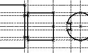
Once the actual drawing graphics is complete, proceed with the drawing layout arrangement. Create dimensions referencing construction lines and nodes. Define hatch contours, their filling patterns and other particulars. Add text entities. When placing text use snapping to nodes and construction lines if desired. This would be necessary if a text is supposed to move together with the drawing graphics.
Further, define GD&T symbols, roughnesses and leader notes. Finally, a complete parametric drawing is created and can further be modified. One can vary construction entity parameters, such as distances between parallel lines, angles between lines, radii of circles.
The graphic entities will subsequently adjust with the construction ones they reference. Thus, a family of variations of the original drawing can be created. All the rest of the drawing layout will also adjust accordingly, all done in an instant.
Note that the above scenario for creating a parametric drawing in T-FLEX CAD is just one recommended technique. One can create construction entities and graphic entities in an arbitrary sequence. What is important is that the graphic entities are constrained to the construction ones.
The following chapters will tell how to use variables as drawing parameters, how to create an assembly from fragments, and much more.
Creating Non-Parametric Drawing (Sketch) in T-FLEX CAD
This technique implies quick sketching of the drawing graphics, completely avoiding preliminary creation of the construction entities.
Sketching supports object snapping and provides dynamic hints that make the drawing process simple and slick. However, thus created drawings do not share the advantage of parametric drawings in the capability of parameter (dimension) modifications. Creating non-parametric drawings may be somewhat preferable in the cases when no significant modifications are expected.
Fast Drawing Creation. Automatic Parametrics
Another method of drawing creation combines the previously described methods – it is used for creating construction-based parametric drawings using commands of non-parametric sketch. The user creates only image lines, using object snapping. T-FLEX CAD automatically "puts" necessary geometrically related construction lines under these image lines. The program defines construction types from the snapping used on creation. For example, for a straight image line parallel to another line the program creates construction line parallel to the construction line of the original image line. The resulting image line will lie on the new construction with parametric relation to the original image line.
Quick Reference on User Interface
This section provides quick reference to T-FLEX CAD while assuming user familiarity with PC operation in general, and some CAD experience as well.
Getting Help
The answers to the questions arising during operation can be got by the following means:
● Help on the current command can be accessed by pressing <F1> key. When no command is active, pressing <F1> invokes the help.
● While within a command, the status bar displays hints and prompts.
● Pop-up help appears when the mouse is placed over an icon, a toolbar or other control element for a brief time. This help message tells the name of the element pointed at, or other related information.
Mouse Interface. Context Menu
T-FLEX CAD operation is mainly performed by mouse. The keyboard is used for inputting numerical values, names, and, in certain situations, for keyboard command accelerators (see below).
Using Left Mouse Button
● Pointing cursor at an icon and pressing ![]() invokes the respective command.
invokes the respective command.
● Pointing cursor at an item of the textual menu and pressing ![]() also does the command call.
also does the command call.
● Pointing cursor at a 2D construction or graphic entity in the drawing window and pressing ![]() selects this entity and activates its editing command.
selects this entity and activates its editing command.
● Pointing cursor at a 2D entity and double-clicking ![]() invokes the "Entity Parameters" dialog box.
invokes the "Entity Parameters" dialog box.
● Pointing cursor at an entity and depressing and holding ![]() while moving the mouse ("dragging") moves the entity.
while moving the mouse ("dragging") moves the entity.
● Subsequent clicking ![]() on 2D or 3D entities while holding left <Shift> key selects a group of entities.
on 2D or 3D entities while holding left <Shift> key selects a group of entities.
● A group of 2D entities can be selected by "box selection" that occurs when the mouse with the depressed ![]() is dragged across the drawing window. The entities will be selected that are entirely within the selection box. If the mouse is moved from left to right the entities will be selected that are entirely within the selection box. The box is drawn with continuous line.
is dragged across the drawing window. The entities will be selected that are entirely within the selection box. If the mouse is moved from left to right the entities will be selected that are entirely within the selection box. The box is drawn with continuous line.
When mouse moves from right to left, the entities are selected with the "cutting" box. This means that the elements both entirely and partially within the selection box will be selected. The box is drawn with the dashed line in this case.
● To unselect one entity in a group of selected, click on it with ![]() while holding left <Ctrl> key.
while holding left <Ctrl> key.
● Pointing cursor at a selected group of entities and clicking ![]() or double-clicking
or double-clicking ![]()
![]() starts moving the selected entities.
starts moving the selected entities.
● Managing libraries and arranging control toolbars can be done using Drag&Drop mode. This is done by pointing cursor at an element, depressing and holding ![]() , and moving to a new location.
, and moving to a new location.
Using Right Mouse Button
● While within most commands, pressing ![]() cancels the last action or quits the command. Certain commands, as, for instance, the spline creating command or the hatch creation, allow user customization of the action performed by the command on the
cancels the last action or quits the command. Certain commands, as, for instance, the spline creating command or the hatch creation, allow user customization of the action performed by the command on the ![]() click. This could be quitting entity creation, canceling last selection, or completing a sequence of inputs.
click. This could be quitting entity creation, canceling last selection, or completing a sequence of inputs.
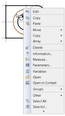
● If no command is active, pressing ![]() invokes context menu. This menu consists of the currently available commands for the given entity. The set of items of the context menu will depend on elements the cursor is pointing at. Thus, it will be different when the cursor is pointing at drawing entities from when the cursor is over a menu area, or toolbar area, or control window area of T-FLEX CAD, etc. To launch a command, point the cursor at the desired line of the context menu and press
invokes context menu. This menu consists of the currently available commands for the given entity. The set of items of the context menu will depend on elements the cursor is pointing at. Thus, it will be different when the cursor is pointing at drawing entities from when the cursor is over a menu area, or toolbar area, or control window area of T-FLEX CAD, etc. To launch a command, point the cursor at the desired line of the context menu and press ![]() .
.
● The context menu can also be invoked while fboxes (see the chapter "ST: Set Document Parameters").
The described right mouse button actions are set as defaults, but can be customized. To do so, go to "Customize|Options…" ("Preferences" tab). For more information, refer to "Customizing System" chapter.
Additional Functions:
If the mouse has a wheel middle button then zooming in/out on the drawing can be done by scrolling the wheel, and panning – by dragging the mouse with the wheel button depressed.
Calling a Command
A command call in T-FLEX CAD can be performed by the following means:
● Using an icon on a toolbar;
● Selecting an item in the textual menu;
● Typing a keyboard accelerator sequence.
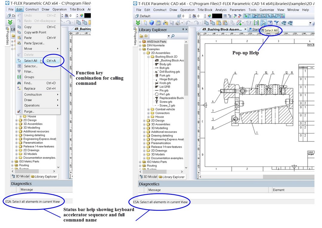
Any T-FLEX CAD command description will begin with a table describing these three ways of calling the command. For instance, consider the command “ESA: Select all elements in current View”. The table will appear as follows:
Icon |
Ribbon |
|---|---|
|
Edit → Edit → Select All |
Keyboard |
Textual Menu |
<ESA>, <CTRL><A> |
Edit > Select All |
The three columns of the table contain the respective calling instructions.
The first column indicates the keyboard accelerator for the command for inputting the command from the keyboard. All key strokes are shown together within one pair of angle brackets. Also, if defined for the command, a standard function key combination is entered next. Each key in the function key combination is shown in its own angle brackets.
The second column contains the access sequence for the command via the textual menu. The name before the dividing line is the name of the appropriate group item in the menu bar. It is followed by the item name in the pull-down menu that stands for the command. The menu item name may be different (abridged) from the full command name, as is, for instance, the item name “Select All” versus the command name “Select all elements in current View”.
The third column of the table contains the icon image for the command. Normally, the particular toolbar containing the icon has the same name as the menu bar group item. For user convenience, a popup with the command name appears when the cursor is briefly held over an icon. Once a command is activated by pressing ![]() on its icon, the icon stays "pushed" up until completing the command or switching to another command.
on its icon, the icon stays "pushed" up until completing the command or switching to another command.
Note: the keyboard accelerator combination is input by pressing the keys sequentially, while the function key combination is pressed simultaneously, i.e. the first key is depressed and held while pressing the second key.
The accelerator sequence for a command can be watched in the prompt field of the status bar when selecting the command in the T-FLEX CAD menu bar or a toolbar. If a function key combination is defined, it is shown on the textual menu item button at the right of the name. Any command allows defining or modifying such combination. See "Customizing System" chapter, "Customizing Toolbars and Keyboard", "Keyboard" tab.
When inputting a command by typing, make sure the system is not within another command, and the status bar is empty.
Each command has an additional set of options and subcommands that can be accessed via the automenu or from keyboard. The keyboard accelerators appear on the pop-ups by the respective commands. Some commands can be conveniently accessed from the context menu. The context menu is invoked by pressing ![]() after selecting one or several elements. The context menu contains a list of commands available with the given selected group.
after selecting one or several elements. The context menu contains a list of commands available with the given selected group.
Canceling a Command
The last action can be cancelled by pressing ![]() in the drawing area or <Esc> key. Repeated pressing quits the command. Alternatively, use the
in the drawing area or <Esc> key. Repeated pressing quits the command. Alternatively, use the ![]() icon of the automenu. Canceling a command clears the command field in the status bar and the automenu.
icon of the automenu. Canceling a command clears the command field in the status bar and the automenu.
Starting System, Saving Drawing, Exiting System
Upon the start of the system the dialog box “Start Page” appears on the screen. It has been explained how to work with this dialog box at the beginning of this chapter. It is worth mentioning again that this dialog box allows creating new documents on the basis of templates already existing in the system, and it shows the list of the recently used documents (with the possibility of opening them). Also, this dialog box has various links, which can be useful in working with the system.
In addition to the dialog box “Start Page”, to create new documents and open already existing ones, the system commands gathered in the textual menu “File” can be used.
"FN: Create New Model" command allows to create a new document:
Icon |
Ribbon |
|---|---|
|
Get Started → Files → Drawing |
Keyboard |
Textual Menu |
<FN>, <Ctrl><N> |
File > New > Drawing |
"FP: Create New Document Based on Prototype" command displays a dialog box that allows to select a prototype file for the new document:
Icon |
Ribbon |
|---|---|
|
Get Started → Files → New From Prototype |
Keyboard |
Textual Menu |
<FР> |
File > New > From Prototype |

O: Open Model command brings up the standard “Open” dialog box to open a document for editing:
Icon |
Ribbon |
|---|---|
|
Get Started → Files → Open |
Keyboard |
Textual Menu |
<O>, <Ctrl><O> |
File > Open |
SA: Save Model command saves the current document:
Icon |
Ribbon |
|---|---|
|
|
Keyboard |
Textual Menu |
<SA>, <Ctrl><S> |
File > Save |
SV: Save Model As command allows the user to save the current document into a new file with a different name without changing the original document:
Icon |
Ribbon |
|---|---|
|
|
Keyboard |
Textual Menu |
<SV> |
File > Save As |
SL: Save All Modified Models command saves all currently open documents:
Icon |
Ribbon |
|---|---|
|
|
Keyboard |
Textual Menu |
<SL> |
File > Save All |
SY: Save current document as prototype for new documents command saves the current document as a prototype for creating new documents:
Icon |
Ribbon |
|---|---|
|
|
Keyboard |
Textual Menu |
<SY> |
File > Save as Prototype |
Once this command is called, a dialog box appears on the screen. This dialog allows the user to specify the name for the prototype file, specify the tab in this dialog box for this prototype or create a new tab if desired, and also delete unnecessary files and tabs.
The prototype files are located in the "Prototypes" folder under the "Program" folder off the T-FLEX CAD home. This is exactly the folder whose content is displayed in the dialog box by default.

A prototype folder can be specified by the command "SO: Set System Options", "Folders" tab.
Save document copy to file with different name command allows to save copy of the document without opening the copy. In this case you can continue working in the source document.
Icon |
Ribbon |
|---|---|
|
|
Keyboard |
Textual Menu |
|
File > Save Copy |
"PS: Show Model Properties" command displays all properties of the current document, and allows to input a brief comment:
Icon |
Ribbon |
|---|---|
|
|
Keyboard |
Textual Menu |
<PS> |
File > Properties |
File > Recent Files displays the list of files open during previous sessions. Select a file name in the list to open. The number of displayed recent files can be set via the Customize > Options > Preferences command.
“FCL: Close Model” command closes the current document:
Icon |
Ribbon |
|---|---|
|
|
Keyboard |
Textual Menu |
<FCL> |
File > Close |
A document can also be closed using the button ![]() , located in the top-right corner of the document window.
, located in the top-right corner of the document window.
"FI: Exit system" command closes the T-FLEX CAD session:
Keyboard input |
Textual Menu |
Icon |
<Alt><F4> |
"File|Exit" |
The system queries the user whether to save modified documents (if any) before exiting.
Function Keys
Certain frequently used commands are bound to function key combinations, as follows:
<F1> |
Get reference information (help) on the current command |
<Alt><F1> |
Get information on the selected element(s) |
<Ctrl><S> |
Save document |
<Ctrl><O> |
Open document |
<Ctrl><N> |
Create new document |
<Ctrl><P> |
Print document |
<Ctrl><F7> |
Recalculate parameters of the current document |
<Alt><F7> |
Regenerate 3D model |
<F3> |
Call ZW: Zoom Window command. This is an instant command that can be called while within another command. The previously active command continues after this command. |
<Ctrl><Shift><PgUp> |
Zoom in |
<Ctrl><Shift><PgDown> |
Zoom out |
<Ctrl><Shift><Left> |
Pan left (moves the model left) |
<Ctrl><Shift><Right> |
Pan right (moves the model right) |
<Ctrl><Shift><Up> |
Pan up (moves the model up) |
<Ctrl><Shift><Down> |
Pan down (moves the model down) |
<Ctrl><Shift><Home> |
Fit to page |
<Ctrl><Shift><End> |
Fit all objects |
<F7> |
Call RD: Update Model Windows command |
<Alt><BackSpace> or <Ctrl><Z> |
Call UN: Undo Changes command |
<Ctrl><BackSpace> or <Ctrl><Y> |
Call RED: Redo Changes command |
Please note that the above command bindings can be changed via the Customize > Customize… > Keyboard command.