Leader Notes |
  
|
Leader Notes |
|
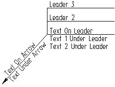
Leader notes are used for decorating various drawing elements. Those mark BOM items, specification of BOM positions points to the locations of brand marks, part codes, etc. A leader note is composed of two parts: the witness line (arrow) and the jog (the leader).
To apply a leader note, you need to specify the position of both parts. Consequently, a leader note has two attachment points. If necessary, it is possible to create leader notes that contain several extension-arrows including bent ones.
Depending on the specified parameters, you can get various detailing elements.
Creating leader notes
Leader node creation is done in the command "IN: Create Leader Note"
Icon |
Ribbon |
|---|---|
|
Draw → Title Block → Leader Note |
Keyboard |
Textual Menu |
<IN> |
Construct > Leader Note |
Creating Simple Leader Note
After launching the command of the leader note creation the following set of options is available in the automenu:
![]() <Enter> Set a leader note attachment point at the position of the pointer
<Enter> Set a leader note attachment point at the position of the pointer
![]() <P> Set Leader Note parameters
<P> Set Leader Note parameters
![]() <Alt+P> Copy Properties from Existing Element
<Alt+P> Copy Properties from Existing Element
![]() <L> Set relation with Line
<L> Set relation with Line
![]() /
/![]() /
/![]() <U> Tie to Arrow/Tie with Angle Fixed/Tie Perpendicularly
<U> Tie to Arrow/Tie with Angle Fixed/Tie Perpendicularly
![]() <N> Select Node
<N> Select Node
![]() <Z> Change Leader’s Orientation
<Z> Change Leader’s Orientation
![]() <F4> Edit Leader Note
<F4> Edit Leader Note
![]() <Esc> Exit command
<Esc> Exit command
To create a leader note, you need to specify subsequently the positions of two points. The first point determines the position of the witness line - the leader arrow, the second - the position of the jog.
The third point appears after the two points positions are specified. The point allows to specify a break. You can create several breaks for the leader note.

When creating the leader note, a dynamic view is fixed to the cursor that entirely shows the future leader note’s view.
After specifying the first snapping point, additional option will appear in the automenu:
![]() <F> Tie to Arrow
<F> Tie to Arrow
The position of the second point can be defined relative to the first point of the leader note attachment (relative to the arrow) or in the absolute coordinates. To select the desired mode, use the option ![]() . With the option turned on, the position of the jog is defined relative to the leader note arrow, otherwise – in the absolute coordinates.
. With the option turned on, the position of the jog is defined relative to the leader note arrow, otherwise – in the absolute coordinates.
Later on when translating the first point of the leader note, created with the enabled option ![]() , the entire leader note will be translated, and for the leader note created with the disabled option
, the entire leader note will be translated, and for the leader note created with the disabled option ![]() , the leader will remain in the initial position.
, the leader will remain in the initial position.
|
||
Option disabled The second point don’t move |
Option enabled The second point moves with the first |
|
Leader note parameters are specified in the command’s properties window before completing the leader note creation with the help of the ![]() option
option
Note that after specifying the last point of the leader note’s arrow the focus is automatically shifted to the text editor. If we press <Enter> in the text input editor - leader note’s creation will be completed. Leader note’s parameters include the contents of the text lines, style of the leader note lines, font style parameters etc. In addition, in the properties window you can specify precise location of the leader note’s snapping points (by specifying the absolute coordinates of the points or their shifts with respect to the selected snapping elements). As with creation of the dimensions, leader note’s parameters can be copied from already existing leader note-element with the help of the |
|
Snapping Leader Note to Drawing’s Elements
Both leader note points can reference a node or a graphic or construction entity. You can select the desired element with the help of ![]() directly in the drawing’s window. To select lines and nodes it is also possible to use the
directly in the drawing’s window. To select lines and nodes it is also possible to use the ![]() and
and ![]() options. When using this mechanism, keep in mind that attaching the second point to a construction line or node is possible only when the option
options. When using this mechanism, keep in mind that attaching the second point to a construction line or node is possible only when the option ![]() is turned off. To cancel of the active attachment-defining mode, press <Esc> or right click
is turned off. To cancel of the active attachment-defining mode, press <Esc> or right click ![]() .
.
To attach a leader note point to a construction entity, first select the desired entity (by clicking ![]() or using the respective option). The entity will be highlighted, and a leader note will start rubberbanding along the entity, following the pointer. Now, specify the position of the leader note attachment point on the entity by clicking
or using the respective option). The entity will be highlighted, and a leader note will start rubberbanding along the entity, following the pointer. Now, specify the position of the leader note attachment point on the entity by clicking ![]() .
.

When attaching a leader note to a straight line, at least one node must exist on the line.
Attaching to a graphic entity is similar to attaching to a construction entity. In the case when the leader note point is beyond the limits of the graphic entity, it will be positioned on the continuation of this graphic entity.
The ![]() ,
, ![]() ,
, ![]() options define the rules of changing location of leader and leader arrow when location of the snapping point is modified. These modes affect only the leader notes that are snapped to lines. When snapping to points there will be no effect if these modes are selected.
options define the rules of changing location of leader and leader arrow when location of the snapping point is modified. These modes affect only the leader notes that are snapped to lines. When snapping to points there will be no effect if these modes are selected.
If the leader note is created with the use of the ![]() option, then upon translation of the leader note along the line it is translated “rigidly” (without changing angles). The
option, then upon translation of the leader note along the line it is translated “rigidly” (without changing angles). The ![]() option allows us to keep the arrow perpendicular to the selected snapping line. The
option allows us to keep the arrow perpendicular to the selected snapping line. The ![]() option allows us to keep the angle that the arrow makes with respect to the selected snapping line.
option allows us to keep the angle that the arrow makes with respect to the selected snapping line.
Markers for Controlling the Snap of Leader Note’s Elements. Creation of Arrow with Bends
After preliminary snapping of a leader note, location of its snapping points can be modified. It is also possible to change the shape of an arrow by creating on it any number of bends. To control snapping of leader note’s points, and also for specifying bends on its arrow, special markers are used.
At the beginning of leader note creation, there are only two markers – they designate the main leader note’s snapping points and are highlighted with blue color. After specifying location of both points, one more marker will appear on the leader note’s arrow image, marked with a green color. This is a point in which an arrow bend can be created. |
|
To correct location of any snapping point of the created leader note, it is sufficient to move the cursor closer to the marker of the desired point (it will be highlighted with orange color) and select it with the help of ![]() . The point will start moving after the cursor. In this way, for example, it is possible to specify the shift when snapping the leader note’s point to the node.
. The point will start moving after the cursor. In this way, for example, it is possible to specify the shift when snapping the leader note’s point to the node.
To create a bend, it is required to move the cursor closer to the green marker (it will also be highlighted with orange color) and select it with the help of ![]() . The arrow will be split into two segments, bend point – arrow bend point – will start moving after the cursor. Pressing
. The arrow will be split into two segments, bend point – arrow bend point – will start moving after the cursor. Pressing ![]() for the second time will fix the location of the arrow bend point.
for the second time will fix the location of the arrow bend point.

After creation of the first bend point, new green markers will appear on the two segments of the arrow. If necessary, it is possible to create the next bend at each of these markers. When arrow creation is completed, you can start creating the next arrow, or complete leader note creation with the help of the ![]() option.
option.
Snapping of each bend point with respect to the previous point of the arrow is controlled by the option:
|
<F> |
Tie to Arrow |
When this option is enabled, the bend point location is specified with respect to the previous characteristic point of the arrow; when this option is disabled – in absolute coordinates.
To remove a bend point, it is required to select it and use the option:
|
<Del> |
Delete Node |
Markers (Manipulators) for Controlling Location of Symbol and Text on Arrow
In the leader note’s parameters it is possible to specify the text and symbol on the arrow. Location of these leader note’s elements can be controlled with the help of the special markers/manipulators.
After selection of the desired marker with the help of ![]() , the symbol or text will start dynamically move after the cursor. You can fix its location by pressing
, the symbol or text will start dynamically move after the cursor. You can fix its location by pressing ![]() for the second time.
for the second time.
Creating Additional Arrows
After specifying location of the main arrow and the leader of the leader note, additional option appears in the automenu:
|
<Space> |
Add Arrow |
As a result of invoking this option, the image of the new arrow will appear next to the cursor.
When creating additional arrows, the same rules will hold as for the main arrow of the leader note. It is possible to tie them to lines and nodes, set relation with dimensions, form bends. In the properties window it is possible to specify individual parameters of the arrow which are different from the ones specified for the main arrow of the leader note.
The end point of an additional arrow can be tied to any characteristic point of the main leader note. To do so, it is sufficient to indicate one of the markers on the leader note image as a snapping point for the arrow’s end.
You can refuse creation of the new arrow by using the option:
|
<Del> |
Delete Arrow |
The list of arrows created for the leader note is displayed in the properties window.

The ![]() and
and ![]() buttons to the left and right of the arrows list can be also be used for creation and removal of additional arrows of the leader note.
buttons to the left and right of the arrows list can be also be used for creation and removal of additional arrows of the leader note.
Automatic Completion of Leader Note’s Creation
By default, after specifying location of two main leader note’s points (locations of arrow and leader), the command remains in the mode of editing the created leader note. This allows us to add to the leader note the desired number of additional arrows, create bends on the arrows, specify and edit leader note’s parameters at any instant of its creation. After finalizing the leader note formation, it is required to explicitly complete its creation with the help of the ![]() option or with the similar button in the command’s properties window.
option or with the similar button in the command’s properties window.
It is also possible to use another work algorithm. In the command’s properties window, in the “Options” section you can find the “Create automatically” flag. When this flag is enabled, creation of the leader note will automatically be completed right after specification of the second snapping point of the leader note (the leader’s snapping point). Note that in this case it is required either to specify parameters of the leader note being created before snapping of the leader or additionally enable the “Show parameters dialog for each element” flag. In the latter case after specifying location of the leader, the leader note’s parameters dialog will appear on the screen. This allows us to work as with the previous versions of T-FLEX CAD – first specify location of an element on the drawing and then specify its parameters. |
|
Leader note parameters
The dialog in the command's properties window contains all main parameters of a leader note. For working convenience, the dialog is divided into several sections.
«Coordinates» Section
The first section, "Coordinates" contains the fields to define the exact coordinates of leader note snap points. The current coordinates are dynamically tracked as the cursor moves in the drawing window.
Depending on the method of leader note snapping, different types of coordinates may be displayed in this section. For example, in the case of the free snap used for both points, the absolute coordinates of both snap points are displayed in the properties window. When using free snapping with the jog being snapped to the arrow, the offsets dx and dy will be used for the second point, relative to the first point, etc.
«Leader» Section
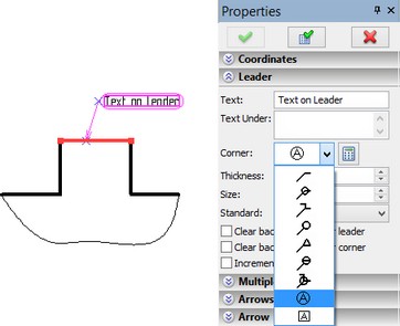
The "Leader" section serves to define all parameters of the leader note jog. Those include: Text. This is the text on the leader note jog. When defining this and other text parameters of a leader note, you can use variables by entering them in curly brackets (braces). Details on that are given for dimensions and text. Text Under. This is the text under the leader note jog. Size. It defines the length of the leader note jog in certain units. If the "Default" value is used, it will automatically assume the length of the text line. Thickness. Defines the thickness of leader lines. If the parameter value is set to "Default", it is calculated based on the "Line thickness|Other lines" parameter defined in the command ST: Set Document Parameters (the tab "Lines"). Corner. Defines the type of the leader jog (see the figure on the right).
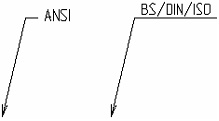
Standard. Serves to define the leader style standard. There are two standards for leaders - ANSI or BS/DIN/ISO. If this parameter is set to "Default", then leader notes will follow the standard specified in the command ST: Set Document Parameters (Detailing elements > Leader Notes > Standard) Clear Backgroung. When this parameter is enabled, the drawing image behind the leader jog (jogs) is erased. Clear Background under corners. When this parameter is enabled, the drawing’s image under the leader note’s corner is deleted. Increment by 1. This parameter is available only at the time of creating a leader note. It serves to quickly define BOM items. A number should appear on the jog instead of text – a BOM item reference number. When the next leader is created, the former current number is automatically incremented by one. It should be noted that when using this approach, the number that appears on the leader will not be related to the BOM position number. |
|
For details about creating BOM item references, refer to the chapter "Setting Positions in Assembly".
«Multiple Leader» Section
Next section of the properties window is – "Multiple Leader" – which contains parameters of additional leader jogs (if any):
Multiple Leaders. This is the field to enter the text on the additional leader note jogs. The jogs in the leader note will be displayed in the order they follow in the window of this parameter. A new jog can be created by double-clicking ![]()
![]() on an empty space of this parameter window (at position of the the next string) or with the button
on an empty space of this parameter window (at position of the the next string) or with the button ![]() . You can modify the order in which leader note jogs follow using the buttons
. You can modify the order in which leader note jogs follow using the buttons ![]() and
and ![]() . To delete a jog, use the button
. To delete a jog, use the button ![]() .
.
String Height. Defines the distance between jogs in a multiline leader note. When the "Auto" setting is used, the distance between jogs is set according to the font size.
Align jogs length. When this parameter is set (default), the jogs in a multiline leader note are drawn with the same length, otherwise – by the length of text lines of the respective jogs.
Append Upwards. This parameter defines the way of placing additional leader jogs. If the flag is enabled, the jogs will be added on top; if the option is disabled, the jogs are added at the bottom (see figures below).

Sections «Arrows», «Arrow», «Text on arrow», «Symbol on arrow»
The following several sections of the properties window – “Arrows”, “Arrow”, “Text on Arrow”, “Symbol on Arrow” – should be described together. They all together allow us to specify parameters for the leader note’s arrows (main and additional).
The “Arrows” section contains the list of all created leader note’s arrows. Buttons to the right of the list allow us to create/remove arrows. By selecting one of the arrows in the list with the help of The “Arrow” section contains следующие leader note arrow parameters: Drop down list for selection of the arrow type at the beginning of extension line. This list mostly coincides with the list of arrows used in the dimension and graphic line creation commands. However, for leader notes the list is appended with two special arrow types: Field for specifying arrow size at the beginning of the extension line. If the “From status” option is selected, the value can be calculated based on the specified parameter «Arrow (end) size» inside the command ST: Set Document Parameters (the «Drawing» tab). |
|
Line thickness. It defines the thickness of arrow lines. In case when the parameter’s value is displayed in square brackets, the value will be calculated based on the specified parameter «Thickness of other lines» inside the command ST: Set Document Parameters (the «Drawing» tab).
Clear Background under arrow. When this parameter is enabled, the drawing’s image under the leader note’s arrow is deleted.
Clear Background under line. This parameter allows us to delete the drawing’s image under the leader note’s arrow line.
Draw leader. This parameter controls drawing of the extension line for the leader note, from the snapping point to the leader note’s arrow.
Clear Background under leader. When this parameter is enabled, the drawing’s image under the leader note’s extension line is removed.
The “Arrow Text” section allows us to specify parameters of the text above and under the selected arrow:
Over line. Text on the leader arrow.
Under line. Text under the leader arrow.
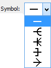
The “Symbol on arrow” section contains parameters of the symbol on the selected arrow:
Symbol. Defines the type of the symbol (see the figure on the right), which will be put in the middle of the leader line. Normally it is used to indicate various drawnig notes. Clear background. With this parameter enabled, the drawing image is erased behind the leader. |
|
Line Width. Defines the thickness of the arrow strokes. In the case when the parameter value is shown in square brackets, it is calculated based on the Other lines parameter defined in the command ST: Set Document Parameters (the tab Lines).
«Options» Section
The section contains following parameters– "Show Dialog for Each Element". If this parameter is enabled, then the leader notes parameters dialog will automatically appear after defining the leader notes position in the leader notes creation command (the option ![]() ).
).
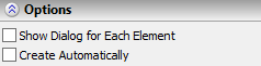
This mode allows working in the same way as in previous versions of T-FLEX CAD – by specifying the leader notes position in the drawing first, and then defining its parameters.
Create automatically. When this parameter is set, creation of the leader note will automatically be completed right after specifying the snapping point for the leader (without pressing ![]() ).
).
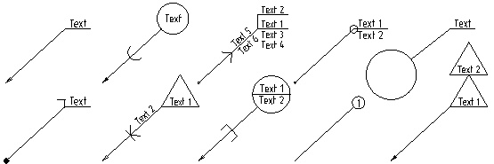
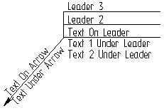
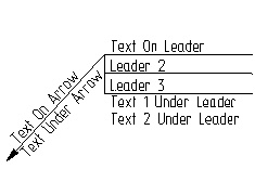
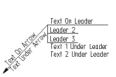
Leader Note Examples
The figures below show leader note appearances with different parameter settings: the first figure represents the state of the properties window as shown above; the second figure is obtained by disabling the "Append Upwards" parameter; the third figure illustrates the case with the disabled option "Align jogs length"; in the case of the fourth figure, the "Leader Height" parameter is set to the value 5.
Leader Note Parameters Dialog
Leader note parameters can also be defined in the parameters dialog called by the automenu option:
![]() <P> Set Leader Note Parameters
<P> Set Leader Note Parameters
The parameters on the tabs of this dialog duplicate the parameters in the properties window. Besides that, the parameters dialog contains several additional parameters. First of all, those are the system-wide parameters: level, layer, priority and color. Also, there is an additional tab in the parameters dialog that contains font settings. There, you can define the necessary font parameters that will be used to display the leader text.
The leader note parameters dialog can also be called in the command-waiting mode from a leader's context menu (accessible by ![]() ). This facilitates quick modification of a leader note's parameters without calling the editing command.
). This facilitates quick modification of a leader note's parameters without calling the editing command.
Defining Default Parameters
The default parameters that will be applied to all newly created leader notes can be defined in several ways.
First of all, those can be defined using the parameters dialog (the option ![]() ). To do that, call the dialog before starting a leader note creation. The parameters defined in it will be copied into the parameters of each newly created leader note.
). To do that, call the dialog before starting a leader note creation. The parameters defined in it will be copied into the parameters of each newly created leader note.
Besides that, you can save parameters of any leader note being created (or edited) as the default parameters, if you click the ![]() button in the command's properties window.
button in the command's properties window.
User's Defined Leader Notes
T-FLEX CAD allows a user to make his own types of notes, more precisely – types for the leaders of notes. User's defined leader notes are created as standard parametric fragments in the library in the folder “System\Leader Symbols” (library “Leader Symbols”).
In the dialog of the leader notes properties, the files located in the given folder are added as icons to the list of the accessible types of the leader. Upon creating the leader note, location of the fragment-leader image is determined by the fixing vector which must exist in the fragment model.
For controlling parameters of the user's leader note, the dialog of the fragment variables or the user's dialog (if it was created in the fragment) will be used. To call the dialog of the fragment variables (or the user's dialog), use the special button ![]() which appears in the dialog of the leader note properties or call the command “Annotation Properties…” in the context menu of the leader note that utilizes the user's leader type.
which appears in the dialog of the leader note properties or call the command “Annotation Properties…” in the context menu of the leader note that utilizes the user's leader type.
Editing leader notes
Editing leader notes is done by the command "EI: Edit Leader Note":
Keyboard |
Textual Menu |
Icon |
<EI> |
Edit > Draw > Leader Note |
|
Upon calling the command, the following icons are provided in the automenu:
![]() <*> Select All Elements
<*> Select All Elements
![]() <Esc> Exit command
<Esc> Exit command
You can select one of the existing leader notes by pointing it with the mouse and clicking ![]() , or you can do multiple selections. As in the case of other drawing elements, multiple selections are done by the option
, or you can do multiple selections. As in the case of other drawing elements, multiple selections are done by the option ![]() . Using
. Using ![]() together with the depressed key <Shift> adds the element to the list of selected, while with the key <Ctrl> - removes from the list of selected.
together with the depressed key <Shift> adds the element to the list of selected, while with the key <Ctrl> - removes from the list of selected.
Upon multiple selections, you can use the options:
![]() <P> Set Leader Note parameters
<P> Set Leader Note parameters
![]() <Alt+P> Copy Properties from Existing Element
<Alt+P> Copy Properties from Existing Element
![]() <Del> Delete selected Element(s)
<Del> Delete selected Element(s)
![]() <Esc> Cancel selection
<Esc> Cancel selection
When selecting a single leader note, the selected element parameters are displayed in the properties window. The following icons become available in the automenu:
![]() <P> Set Leader Note parameters
<P> Set Leader Note parameters
![]() <Alt+P> Copy Properties from Existing Element
<Alt+P> Copy Properties from Existing Element
![]() <O> Create Name for Selected Element
<O> Create Name for Selected Element
![]() <W> Link to Product Structure
<W> Link to Product Structure
![]() /
/![]() /
/![]() <U> Fixing to Point/Angle Fixing/Orthogonal fixing
<U> Fixing to Point/Angle Fixing/Orthogonal fixing
![]() <Space> Add Arrow
<Space> Add Arrow
![]() <Z> Change leader line jog
<Z> Change leader line jog
![]() <Del> Delete selected Element(s)
<Del> Delete selected Element(s)
![]() <Esc> Cancel selection
<Esc> Cancel selection
The general principles of the command "EI: Edit Leader Note" are similar to other editing commands. Keep in mind that a leader note has two or more (when there are bends or several arrows) attachment points. The positioning and attachment of each point is edited separately.
Select a leader note using ![]() . Now you can modify the position of either point of the leader note. To do this, move the pointer to the desired point and again click
. Now you can modify the position of either point of the leader note. To do this, move the pointer to the desired point and again click ![]() . At this moment, the following additional options will appear in the automenu:
. At this moment, the following additional options will appear in the automenu:
![]() <F> Attach to arrow (available only when selecting the second attachment point of the leader note)
<F> Attach to arrow (available only when selecting the second attachment point of the leader note)
![]() <L> Set relation with Line
<L> Set relation with Line
![]() <N> Set relation with Node
<N> Set relation with Node
![]() /
/![]() /
/![]() <U> Fixing to Point/Angle Fixing/Orthogonal fixing
<U> Fixing to Point/Angle Fixing/Orthogonal fixing
![]() <T> Link To Node (only when selecting a point snapped to the node with a shift)
<T> Link To Node (only when selecting a point snapped to the node with a shift)
![]() <K> Break (kill) relations (only when selecting a point snapped to the node, line)
<K> Break (kill) relations (only when selecting a point snapped to the node, line)
![]() <Z> Change leader line jog orientation
<Z> Change leader line jog orientation
Upon selecting a point, you start rubberbanding the leader note by the selected point.
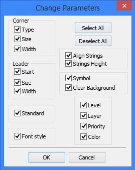
Now, you can fix the new position of the leader note attachment point. You can also break the attachment link using the option <K>, or attach the leader note to a node or construction entity. Editing leader note parameters in the case when a single element is selected is similar to defining leader note parameters. The option ![]() allows modifying the parameters of several selected leader notes. The option <P> brings up the dialog box "Change parameters". In this dialog box, check the parameters that you want to edit. By default, all the parameters of the selected elements are subject to editing. If a parameter is not supposed to be changed, clear the respective check box. Upon selecting the parameters for editing and pressing [OK], you get the access to the standard leader note parameters dialog box. The parameters that were check marked are available for editing.
allows modifying the parameters of several selected leader notes. The option <P> brings up the dialog box "Change parameters". In this dialog box, check the parameters that you want to edit. By default, all the parameters of the selected elements are subject to editing. If a parameter is not supposed to be changed, clear the respective check box. Upon selecting the parameters for editing and pressing [OK], you get the access to the standard leader note parameters dialog box. The parameters that were check marked are available for editing.
Option ![]() takes parameters from another leader note.
takes parameters from another leader note.
The option ![]() allows linking the leader note to a record (entry) in product structure window. Calling this option brings up the window "Product Structure".
allows linking the leader note to a record (entry) in product structure window. Calling this option brings up the window "Product Structure".
To add the new jogs open "Multiple Jogs" tab of the properties dialog, select the desired item from the "Product Structure" and press <Ins> or button ![]() . After that, new position number will appear in "Multiple Jogs" and on the drawing.
. After that, new position number will appear in "Multiple Jogs" and on the drawing.
Option <Del> allows deleting a leader note jog, when there are several, while options <Alt+Up>, <Alt+Down> - changing the order of the leader note jogs.
More details about connection with the product structure can be found in chapter "Bill of Materials".