Loft |
  
|
Loft |
|
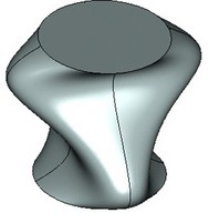
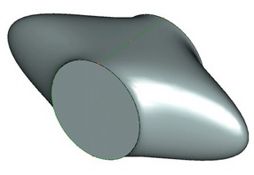
This operation creates solid bodies of complicated shapes. The command has united the three former commands, "Lofting", "Net Surface" and "Ruled Solid". The Loft operation can be built on practically any model elements based on one of the three principal geometry types, "point", "wire" and "sheet". Depending on the geometry type of the base elements, the result may be obtained in the form of a solid body or a set of surfaces. The resulting spline surfaces are constructed based on the specified set of sections and guides subject to the imposed boundary conditions. An optimization module is available among the operation settings that forces generation of simple analytical surfaces whenever possible.
Main concepts. Operation capabilities
"Point" in the three-dimensional space can be defined by a 3D node, a 3D vertex, or a "position" parameter on an object. The "wire" geometry elements (the ones with length/perimeter but without area) include all linear objects – edges, 3D paths, loops and some types of 3D profiles. Some times, the system can automatically extract geometry of the required type from the sheet objects, such as faces. "Sheet" objects (with area, but without volume) include all types of surfaces, faces and 3D profiles created from a closed contour. Sometime an operation is accepted as a sheet object, if the operation results in a surface (a set of surfaces).
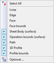
While selecting elements, always pay attention to the active object selection filters. These are convenient, as, generally, pointing the cursor to a group of elements may not identify the specific desired element. Thus, for example, if we need to select just an edge on the profile rather than the whole profile, the filter should be set up for edge selection. To turn on the necessary filter, one can use the pull-down list under the currently active option of the automenu. The options possessing such pull-down lists are marked by a black triangle in their lower-right corner. The list of the available filters under a particular option is accessed by pressing and holding To turn on one filter and simultaneously turn off all the rest, push the filter button with |
|
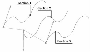
Sections
Sections define the surface shape along the first direction. To create a simplest instance of the operation, at least two sections need to be selected.
A section can be represented by either a sheet or a wire object. A wire object may be either closed-loop or open. One section can be composed from several pieces that can be freely added and removed during the operation setup. The set of objects making one section must have same-type geometry. For example, one section can be composed of a set of paths and edges, or, alternatively, of a set of adjoining faces.
The contours of all sections used for creating the resulting surface must be of the same type – either open or closed. Exception is the case of a "clamped tube" body. In that case, most sections are defined by closed-loop sections, while the first or last section is defined by an open "wire". In order to successfully create such a body, follow precisely the set of conditions listed below.
Multi-contour profiles can be used as sections, if they have same topology. For example, these can be similar profiles or copies of the same multi-contour profile. In this case, no other parameters may be specified (guides, matches, boundary conditions).
A point can be used as the first and last section. In this case, the surface will collapse in the selected end points.
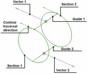
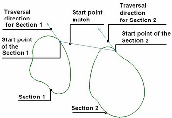
A section possesses such a property as the direction of the contour traversal. When defining the operation, an arrow is drawn on the selected section indicating the contour direction The contour direction is used for computing the surface, it should match for all selected sections. In most cases, the system can automatically determine the contour directions for successful creation. However, if necessary, it can be flipped by the user for each individual section.
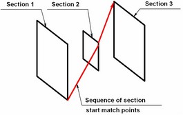
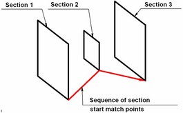
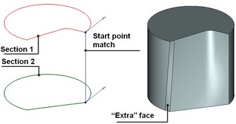
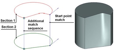
Match points
The match points help defining the direction of the surface propagation between the characteristic points of different sections. Always there is at least one match between the points in the sections. Originally, it is set between the start points of the sections. New sequences of match points can be added by the user manually. Any sequence of match points, including the start points, can be edited. The preview of the operation in the 3D window displays each set of match points connected by straight lines as soon as the elements get selected.
In the case of open contours, the start points can only be defined at the start or end of a section.
Each set of matching points includes one point from each section, except for the end sections defined by a single point The match points can be defined by 3D nodes, section vertices or the points defined on a section edge by the "position" parameter.
If the end sections are open with the rest closed (as in the "clamped tube" body type), then the following conditions must be met when defining the match points:
1. At least two sequences of match points must be defined passing through the start and end of the first and last open wire.
2. The closed profiles should not have "free" vertices, that is, the vertices not used as match points in any sequence.
3. All match point sequences must meet at the start or end of the first and last open wires.
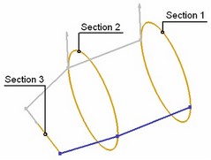
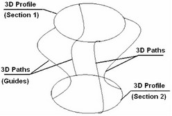
Guides
Guides are similar to sections and are used for defining the shape of the resulting surface in the second direction. As opposed to sections, the guides can be made of wire geometry only. If a sheet object is selected, its perimeter will be used instead. All objects must have continuous first derivative, that is, the "wire" should not have any sharp corners. Another condition is the requirement for a guide to intersect with all sections, including the ones defined by a single point. One guide can be composed of several smoothly connected linear objects.
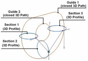
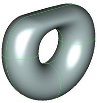
Guides can be closed or open. Closed guides are used for creating closed bodies.
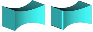
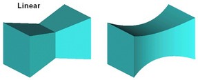
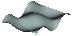
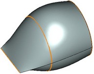
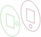
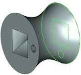
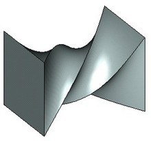
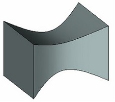
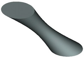
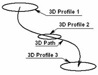
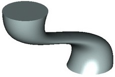
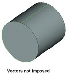
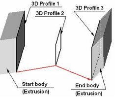
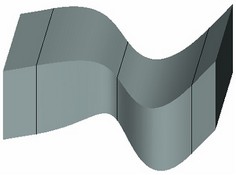
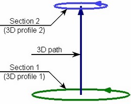
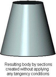
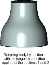
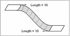
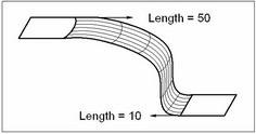
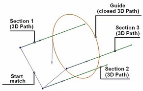
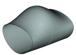
Instead of guides, one 3D path can be used, as if replacing multiple guides passing through all section points. The path defines the boundary conditions for t and he entire resulting surface. Therefore, other boundary conditions are not subject to being defined when the guide is defined. The only exception is the option of specifying the tangent direction with respect to the surface being created as derived from the path at the point where it intersects the section defined by the 3D profile (see below). A path is not required to intersect with the sections. The diagrams following below demonstrate the operation created with neither a path nor guides (left) and the one using a 3D path (right).
Boundary conditions
Boundary conditions impose additional constraints on the shape of the resulting surface.
The following boundary conditions can be defined for all sections and guides, except for the case of using a single 3D path as a guide:
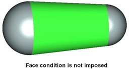
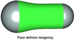
●Faces – these help define the first derivative (the direction) at each point of the section edge and at a segment of a guide, or the second derivative (the curvature) only for a section edge. The direction is derived from the face at the tangency point between the face and the frame edge. The face specified for defining the condition must end at an edge of the section or guide on which the condition is being imposed.
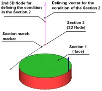
●Vectors – these are used for defining the first derivative (direction) of the resulting surface at an arbitrary point on a section contour or guide.
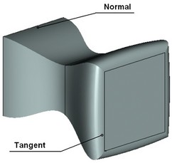
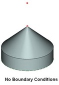
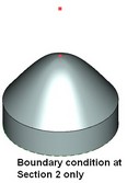
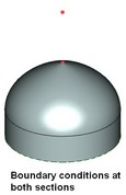
The following boundary conditions are applicable at the start and end sections: ●Normal (outside) – the resulting surface is constructed orthogonal to the section plane. The normal vector is computed automatically and always points outside of the body to be created. ●Normal (to profiles) – same as the above. The normal vector is derived from the profile. This is a legacy functionality of earlier T-FLEX versions. ●Tangent – the resulting surface is constructed tangent to the section plane. |
|
The above three conditions can be defined only for sections that are planar or are actually a part of a plane.
●Body – the body providing the tangency condition. The body must directly adjoin the section by one of the faces, with the face preferably matching the section The tangency condition (the directions) is derived from the side faces of the body.
The boundary conditions for the start and end sections – points can be defined as a normal vector of a plane passing through the point. The resulting surface will be made tangent to thus defined plane.
All boundary conditions for sections listed above are mutually exclusive. This means, the same area or point may not be assigned several boundary conditions. No conditions are allowed on the end sections in the case of a closed surface.
Different boundary conditions may conflict. Only one face should correspond to a section edge or guide. If more than one face relates to an edge then the boundary condition is ignored, and the system outputs an appropriate warning. A boundary condition may not be defined by a vector at the intersection of a section and a guide. Two vectors should not be defined in the same point either.
If a single 3D path is defined instead of guides, then only one type of boundary conditions can be specified for the surface being created, which is the 'tangent to path' condition at the point of the path's intersection with the section. The section to which this condition applies must consist of a single 3D profile. The boundary condition is defined by selecting a face of the profile, on which the section definition was based.
Loft operation defining steps
The operation creating command can be called via one of the following ways:
Icon |
Ribbon |
|---|---|
|
3В Model → Create → Loft |
Keyboard |
Textual Menu |
<3SL> |
Operation > Loft |
The property window and the automenu are used for handling the command and defining necessary components. These work simultaneously and enhance each other. The state of the automenu depends on the operation defining stage and on the purpose and type of the objects being selected. The object selection modes can be manipulated via either the automenu or the property window.
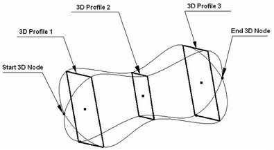
The surface of the operation is computed based on the element skeleton and specified boundary conditions. The skeleton elements are sections and guides.
To create the operation, follow the following steps:
1. Define sections
2. Define guides (optional)
3. Define match points (optional)
4. Define boundary conditions (optional)
5. Confirm operation creation
Section selection
The operation is always defined beginning with selecting the sections. For successful operation creation, at least two sections are required. Any system object may be used as a section that contains wire or surface geometry.
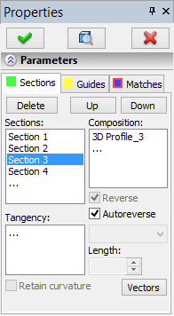
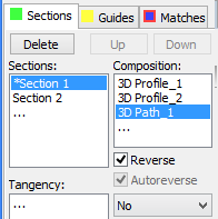
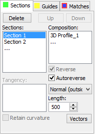
To start the section selection mode, focus (click) at an empty line in the "Sections" pane. This area is on the [Sections] tab of the property window. The automenu will then automatically switch to section selection mode.
The following options become active.
This option is responsible for section selection mode.
This option provides fine tuning of the filters for selecting objects. The black triangle in the lower-right corner of the icon indicates availability of the pull-down list. Then, proceed with selecting objects in the 3D window. Each selected element will be appended in the end of the sections list as another section. Sections can be moved up and down the list with the help of the respective dialog buttons. To remove any object from the list in all three panes of the dialog, highlight the object in the list and press the [Delete] button or the <Del> key. Restrictions: The start and end sections may not be moved around the list if these are defined by points, or if boundary conditions are defined there specific to the start and end sections. |
|
Each section may be composed of several objects of the same type. The "Composition" pane shall be used for defining such complex section. This pane displays the list of names of the selected elements for each particular section. To add to the section contents, focus (click) at the "Composition", pane and then select additional objects. Restrictions: A section may be composed only of the objects of the same geometry type. |
|
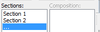
If for some reason the system runs into an error while composing a section contour, this section will be marked by the "*" symbol. This may happen due to various reasons. For example, gaps were produced during model regeneration, or elements disappeared that were part of a section. |
|
By default, the smooth edge chain selection mode is turned on. In this mode, selecting one edge automatically results in selection of smoothly adjoining edges to the selected one, that is, making the selected edge continuation with the continuous first derivative, with no sharp corners. Turning the mode on/off is done via the respective automenu option:
![]() <G> Smooth edge chain selection mode.
<G> Smooth edge chain selection mode.
Point objects – 3D nodes and vertices can be selected as the ending sections (start or end). To define such section, activate the following automenu option:
![]() <E> Select 3D Node
<E> Select 3D Node
By switching between the selector filters one can select any objects defining a point in the three-dimensional space: a 3D node, 3D vertex, center of an arc, center of a sphere, a coordinate system. The new section – point will always be at an end, in the beginning or the end of the list of sections.
Operation skeleton display when defining sections
The elements selected as sections are highlighted in green by default. The active section is highlighted in red. Active considered the section that is being currently manipulated. For example, working on a section composition makes it active. Settings of the highlighting colors are done in the system customization dialog box.
The colored square on the [Sections] tab is filled with the color of the current highlighting setting of the sections.
A start point is set for each selected section. The set of start points makes the first match sequence. If sections are closed then the start point is set in the nearest to the cursor vertex of the section. For open sections, the start point is set in the nearest end of the "wire". If the system-defined configuration of the section starts is not suitable, it can be changed, or new matches can be added. The detailed description of section matching follows below. An arrow is displayed at each section start indicating the contour direction. The same direction should be defined in all sections for successful operation creation. A contour direction can be flipped by toggling the "Reverse" flag. Toggling the flag moves the start arrow to the opposite end of the contour.
In the case of closed contours, the system attempts to synchronize the contour directions automatically, using the "Autoreverse" option.
Defining match points
Once the sections are defined, the system needs to relate them with each other. One needs to define how to configure the surface. One match sequence is automatically created from the start points once the sections are defined. In complicated cases, however, this may not be enough.
The sections are divided into sectors by the match points. Some of the generatrices of the surface being created pass exactly through the match points. The space between the sectors is divided into an equal number of elements for the primary generatrices to pass through. Should there be at least one vertex within a sector between any two match points on a section, the system subdivides the respective matching sectors in all sections in the same proportion. This is done to achieve an equal number of sectors in all sections. This may lead to creation of additional, sometimes undesired, edges and faces. Therefore, an optimum solution is to define match points in the vertices of the sections. This way of defining the match points should be favored whenever possible. To switch to match point defining mode, go to the [Matches] tab of the operation property window. This tab hosts two related panes with the lists of sequences and the respective match points. Each sequence contains one point per a section, except for the single-point sections. The points are ordered from the start to the end section. The contents of the sequence can be viewed in the second pane, named "Points".
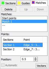
To define a new sequence, place the cursor at an empty line in the "Matches" pane. The system is now ready for defining the points. The following options get activated in the automenu.
![]() <C> Define match points
<C> Define match points
This option sets the mode of match point selection.
By default, all three types of points are selectable in the command. The automenu lets setting up a filter for selecting just one type of object: nodes only, vertices only, or points on edges. The following automenu options are used for such setup:
![]() <A> Select All Points
<A> Select All Points
![]() <N> Select 3D Nodes
<N> Select 3D Nodes
![]() <X> Select Vertices
<X> Select Vertices
![]() <K> Select Points on Edges
<K> Select Points on Edges
The first section is activated and is automatically highlighted in red (by default) in the 3D view window. Once a point is selected on the first section, the second section gets highlighted, and so on, until points are selected in all sections. All vertices of the active section are highlighted as well. The object snapping turns on, helping to bind a point to a section vertex or a 3D node on the section.
If snapping to vertices and nodes is not required then the point can be placed on a section edge. In this case, the point position on the edge will be defined by a parameter varying from 0 (at the edge start) to 1 (at the end of the edge). The edge direction is same as the contour traversal direction.
A point can be selected by pointing the cursor to the desired object and clicking ![]() . Object selection occurs per current filter settings.
. Object selection occurs per current filter settings.
The "Automatic" flag is used for automatic placement of the match points. The automatic match points can only be defined for flat closed contours under the condition that at most one section is allowed to have the discontinuous first derivative (a sharp corner). As the "Automatic" flag is cleared, the points created automatically are converted to the modifyable objects.
RESTRICTION: Intersecting match point sequences are not allowed.
To edit a sequence or point object, simply select it in the property window, after which redefine it by selecting another object in the 3D window. Thus, to edit a whole sequence (say, the start point one), select the object "Start points" on the "matches" tab, and then pick one by one the desired points on each section. Highlighting and object snapping work just as at the initial sequence definition. To edit a particular point in the sequence, first select this point in the list of the "Points" pane, and then select another object in the 3D window. The respective section is highlighted while editing a point.
Upon finishing editing of the selected object, the system proceeds with the next object in the list – a point or a sequence, or offers to define a new sequence, if the edited object was last in the list.
To remove any entry from any pane, select it and press the <Del> key or the [Delete] button.
Guide selection
The guides are side elements of the operation skeleton. Guide definition is mostly similar to the section definition procedure.
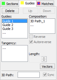
To switch to the guide definition mode, go to the [Guides] tab of the property window. Just like the Sections tab, this one hosts three panes, "Guides", "Composition" and "Tangency". The latter will be used when defining boundary conditions (see below). If an error occurs while composing the contour, then the guide is marked by "*". To select a new guide, click at the new line of the "Guides" pane. The new line is marked by an ellipsis. Upon switching to the tab, the automenu enters the mode of guide selection. The necessary options become available.
This option sets the guide selection mode. For convenience, the necessary object selection filters can be set up. The filter buttons are located on the system toolbar or in the pull-down lists of the appropriate automenu options.
This option provides fine tuning of the filters for selecting objects. The black triangle in the lower-right corner of the icon indicates availability of a pull-down list. By default, the smooth edge chain selection mode is turned on. |
|
![]() <G> Smooth edge chain selection mode.
<G> Smooth edge chain selection mode.
The elements can be selected in the 3D window or in the model tree.
RESTRICTION: A guide must intersect with all sections, including the single-point ones.
Operation skeleton display when defining guides
The elements selected as guides are highlighted in yellow by default. The active guide is highlighted in red. A guide becomes active as it is selected in the list of guides. Settings of the highlighting colors are done in the system customization dialog box.
The colored square on the [Guides] tab is filled with the color of the current highlighting setting of the sections.
An arrow is displayed on each guide indicating the traversal direction. The direction should be from the start to end section for successful operation creation. The direction is defined automatically for open guides. The traversal direction of a closed contour can be flipped by using the "Reverse" flag. When closed contours are used, the system tries synchronizing the directions in the "Autoreverse" mode.
3D paths used instead of guides.
The direction of the loft surface construction can be defined in each section.
This functionality is kept primarily for compatibility with older versions. When creating a loft operation anew, guides and boundary conditions should be used for full control over the shape of the surface.
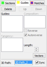
To enter the mode of path selection, click the mouse inside the "3D path" pane. The option will activate in the automenu:
![]() <W> Select 3D Path for Sections orientation
<W> Select 3D Path for Sections orientation
Then a 3D path can be selected in the 3D window or in the model tree. The specified path affects the body shape as follows: Vectors are defined for all match points of all sequences from a match point to the nearest point on the path. The body surface is then computed using the minimum twist algorithm. To successfully create the operation, it is necessary that the selected path is oriented from the first section to the last one. If the “Sync” flag is set in the properties window, the system will automatically change the direction of the selected path as necessary. To reject a path selection, place the cursor in the "Path" pane and press the <Del> key or the [Delete] button on the dialog. The second direction can be defined by either guides or a path, and not both. If a path is used, the guide selection is blocked. Vise versa, if at least one guide has been specified, then the "Path" pane becomes inaccessible. |
|
Defining boundary conditions
Different boundary conditions can be defined for different operation components. These are defined in order to achieve a surface closely matching the design intent, including various blending features.
Conditions on ending sections
These boundary conditions are specific to and can only be defined for the start and end sections, if these sections are based on flat contours. The geometrical information contained in a flat contour is sufficient to determine the rules of the surface construction in the area near the given section.
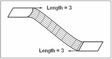
A choice of only two conditions, how the surface meets the section, is available – orthogonal or tangent to the section plane. The degree of surface twisting is defined by a number representing the vector length. The following steps are to be done in order to define such boundary condition: 1. Select the desired ending section in the full list of sections. The selected section becomes active and is highlighted in red. 2. If the geometry of this section is appropriate then the list will become accessible on this same tab of the dialog containing the following four conditions: "No", "Normal (outside)", "Tangent", "Normal (to profiles)". Select the desired condition. 3. Enter the desired numerical value in the "Length" box. |
|
The value is entered in the absolute model units. Therefore, the required value depends on the size of the model. Large models require greater values for achieving the same expected result.
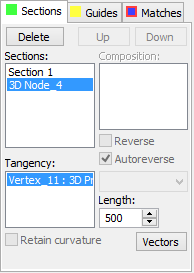
Boundary conditions on the ending sections can be defined by tangency to bodies. The spline surface will be created in this case tangent to the faces of the selected bodies adjoining to the section.
To define such boundary condition, do the following steps:
1. Select the desired ending section in the full list of sections. The selected section becomes active and gets highlighted in red.
2. Click the mouse at the "Tangency" pane. If an ending section was selected then the body selection option activates in the automenu (another available option in the automenu for face selection is described below).
![]() <B> Select Solid for setting beginning condition
<B> Select Solid for setting beginning condition
![]() <B> Select Solid for setting ending condition
<B> Select Solid for setting ending condition
The option appearance depends on whether the start or end section is active.
3. Select a body. The section being processed must match with a face on the body. The surface being constructed will be made tangent to the adjoining faces of the body.
Conditions for sections defined by single 3D point.
A plane can be constructed through a single point section. The surface collapsing at an ending single-point section will be made tangent to this plane. To define the plane in space, an additional object is required to define the direction of the plane normal. The surface curvature is defined by the vector length.
The following steps are to be done in order to define this boundary condition: 1. Select the desired ending section in the full list of sections. 2. Click at the "Tangency" pane. If a single-point section is selected then the following options become available in the automenu for selecting new objects :
The first option sets up the filters for selecting points (3D nodes, vertices etc. The second option is designated for selecting direction-defining objects, such as straight edges, paths, profiles, axes of revolution for rotation operations, coordinate systems, etc.
|
|
3. Using one of the options, select a point or direction in the 3D window. Upon selection, the name of the selected object will be displayed in the "Tangency" pane.
4. Specify the vector length. Do this by entering a value in the "Length" input box.
Conditions for arbitrary sections and guides
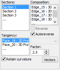
The boundary condition can be defined for any sections and guides by faces. Subject to certain restrictions, such condition may define the direction (the first derivative) or the curvature (the second derivative) of the surface being created in the area near the currently active element.
To specify a boundary condition by faces, do the following steps:
1. Select the element subject to the boundary condition being defined. The sections are selected from the "Sections" pane on the [Sections] tab, while the guides are from the "Guides" list on the [Guides] tab. The selected element becomes active and is highlighted in red.
2. Click the mouse at the "Tangency" pane. The option for selecting tangency surfaces activates in the automenu:
![]() <F> Select Tangent Faces
<F> Select Tangent Faces
3. Select a face in the 3D window that will define the boundary condition at the section or a guide. If several faces adjoin the skeleton element, select them all. While doing so, keep in mind the following restrictions:
●The current element (a section, a guide, or a segment thereof) must fully lie on the selected face
●The selected face must end at the active element
●If two skeleton elements intersect, their respective faces must define the same direction. This means, if guides are defined in the operation then this boundary condition is not acceptable for a whole section. In some special cases, when open sections are used, the system allows using this boundary condition when one guide is present.
In the case of violating these restrictions, the tangency condition is ignored and a respective message is output in the diagnostics window.
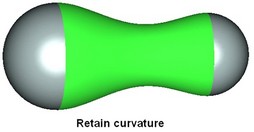
It follows from the above that the considered boundary conditions can only be specified at certain segments of a guide. The guide meanwhile must be defined by a set of smoothly connected elements. The selected faces are highlighted in green (by default). 4. Enter the value in the "Length" input box for the selected tangency surfaces. This value determines the degree of the boundary condition influencing the curvature of the surface being created in the area near the current skeleton element. 5. Turn on an additional flag "Retain curvature" (optional). This will insure existence of second derivatives in the area where the current skeleton element meets with the selected faces. Without this, only first derivatives are guaranteed. |
|
Please note that when using a single 3D path definition, the face boundary conditions can be specified only for the sections defined by the 3D profile. In this case, you can only select the face of that 3D profile as the face definition.
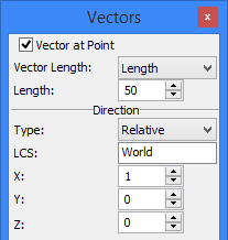
Boundary condition vectors
A boundary condition can be defined by a vector at any point on the skeleton elements of the Loft operation, such as a point, a section, a guide or a match point.
Vectors are defined in a special dialog box launched be pressing the [Vectors] button in the operation dialog. This button is present on all three tabs of the operation dialog. The Vectors dialog box will stay up even when switching between the tabs of the operation dialog. Its contents change depending on the operation mode and on what operation element is currently active.
I. Defining vector on skeleton elements
The following steps need to be done in order to define a vector based on a section or a guide:
1. Select the skeleton element to base the vector upon. For this, switch to the respective tab of the operation dialog and select the skeleton element from the list. Upon selecting a section or a guide, this skeleton element becomes active and gets highlighted in red.
2. Call the vectors dialog box by pressing the [Vectors] button.
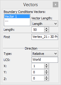
3. Click the mouse over an empty line with the ellipsis symbol in the "Boundary Conditions Vectors" pane of the vectors dialog. The system enters the vector-defining mode. All vertices of the active section/guide get highlighted. The following filter tuning options appear in the automenu:
![]() <A> Select All Points
<A> Select All Points
![]() <N> Select 3D Nodes
<N> Select 3D Nodes
![]() <X> Select Vertices
<X> Select Vertices
![]() <K> Select Points on Edges
<K> Select Points on Edges
The first option is active by default.
4. Define the vector in space. There are several ways of defining a vector. The difference is in the ways of defining the start point, direction and the length of the vector.
The start point can be defined as follows:
●At a vertex on the section/guide. Pick with the cursor one of the section/guide vertices. The name of the vertex is entered in the "First Point" box of the Vectors dialog. ●In a 3D node constructed on an edge of the section or guide. Pick a 3D node with the cursor on the section (guide). The name of the 3D node is entered in the "First Point" box of the Vectors dialog. ●At any position on any edge of the section (guide) by defining the parameter of the point position on the edge. The point is created by picking anywhere on the section (guide) edge. The edge name is entered in the "First Point" box. The position of the point is defined by the parameter along the edge. The parameter takes values from 0 to 1 and can be modified. |
|
The vector-indicating arrow is drawn from the selected point on the skeleton in the 3D window.
Upon specifying the start point, additional parameters become accessible in the Vectors dialog box for defining the vector direction. The direction of the vector can be defined in one of the following ways:
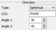
●In absolute coordinates, assuming that the start point of the direction vector is located at the origin, <0,0,0>. With optional selection of a local coordinate system, the direction is computed in the relative coordinates.
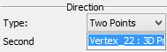
●In spherical coordinates. Two angles must be specified to define the vector direction. ●By selecting the end point. Select an object defining a point in the three-dimensional space – a 3D node, a vertex, an arc center, etc. When switching to the direction defining mode by the second point, the automenu provides the following option with a pull-down list of filters:
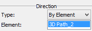
●From a direction-defining element. This can be an edge, an arc, a face, a flat 3D path or 3D profile, a surface of revolution, a coordinate system. The direction is derived from the element itself. It can be, for example, the normal direction to a flat element, or the direction along an axis of revolution. The following option activates in the automenu when defining the direction from an element:
|
|
To define a local coordinate system, click in the "LCS:" box. The following option will appear in the automenu:
![]() <L> Select LCS.
<L> Select LCS.
Select a local coordinate system in the 3D window or in the model tree. This will let you define coordinates of the direction vectors relative to the selected coordinate system. A separate coordinate system can be defined for each vector.
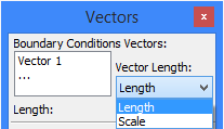
5. A section allows vector conditions of two types. The type of a condition is defined for all vectors constructed on one skeleton element simultaneously. The selection is done from the list in the Vectors dialog box: ●Vector length definition. ●Scale factor definition. In this case, the operation automatically computes the absolute value of the derivative along the specified direction and multiplies it by the scale factor. |
|
6. (Optional). More than one vector can be defined for a single skeleton element. To define a new vector on a skeleton element that is already in use, proceed to the item 3.
II. Defining vectors at match points
The vector is defined at a match point according to the same rules as the ones described above for the skeleton elements.
The only difference is that the match point selected for defining a vector becomes automatically the start point of the vector. Do the following steps to define a vector at a match point: 1. Switch to the [Matches] tab of the operation dialog. 2. In the "Matches" list, select the desired sequence of match points. 3. In the "Points" list, select the desired match point. 4. Call the Vectors dialog box by pressing the [Vectors] button. 5. Set the "Vector at Point" flag. This creates a new vector in the selected match point. 6. Define the vector direction and length (see above). |
|
Using the created loft in a Boolean
To create a Boolean operation, do the following:
1. Turn on the Boolean creation mode by the automenu option
![]() <Ctrl+B> Select original body for Boolean operation
<Ctrl+B> Select original body for Boolean operation
A Boolean is created when the icon is pushed.
2. Select the type of the operation from the pull-down list under the above option:
![]() <Ctrl+'+'> Addition
<Ctrl+'+'> Addition
![]() <Ctrl+'-'> Subtraction
<Ctrl+'-'> Subtraction
![]() <Ctrl+'*'> Intersection
<Ctrl+'*'> Intersection
![]() <Ctrl+l> Smart mode
<Ctrl+l> Smart mode
Operating principles of the Smart mode:
●If the body being created and the existed selected body have intersection of volumes - the type of Boolean operations: subtraction.
●If the body being created lies entirely within the selected body - the type of Boolean operations: subtraction.
●If the body being created touches and selected body touch each other - the type of Boolean operations: addition.
●If conditions set out above are not met, or a selected body lies inside the created, or error occurred determining the type of penetration, then, Boolean type is not defined - the Boolean operation will not be created.
3. Select the target body for the Boolean (optional in some cases), using the automenu option
![]() <Ctrl+T> Select Target Body for Boolean
<Ctrl+T> Select Target Body for Boolean
If only one body exists in the scene, it is selected automatically. The new body created by the extrusion operation becomes the tool body of the Boolean.
Upon confirming operation creation, first the body is created by the loft operation, and then the specified type Boolean is performed.
Setting additional operation parameters
The "Periodic" flag is used for creating closed bodies or surfaces. If this flag is set, the end section will be connected with the start. This parameter can be set if the start and end sections are not single-point sections and if no special conditions are defined for the start and end profiles.
If guides are used together with the "Periodic" attribute then the guides must be closed.
The "Linear" flag – if set, ruled surfaces are created, splines otherwise. A ruled surface is produced by sweeping a straight-line generatrix between two sections. The flag "Thin-walled". If sections are defined by elements of sheet geometry then this attribute defines creation of a surface instead of a solid body. |
|
Optimization Parameters
The “Tolerance” parameter specifies the maximum allowed gap between profiles and guides. Thus, for example, setting rough (large) tolerance in some cases allows handling a situation when the sections and guides do not intersect, but pass near each other. The tolerance defines the distance between them that the system can ignore by assuming that the guides and sections do intersect. Besides, the tolerance affects the minimum size of a profile edge that is defined as ten times the tolerance value. Consequently, the same limit is used as the minimum distance between two distinct match points on a profile, as well as between start points of boundary conditions defining vectors. The lower tolerance limit is 10-8. However, keep in mind that a too small tolerance may slow down the system operation. The system default tolerance is 10-5.
The “Simplify geometry” flag is used for simplifying the geometry and topology of the resulting surface. With this flag on, analytical surfaces are created instead of splines whenever possible, such as a torus, a cylinder, a sphere and a plane.
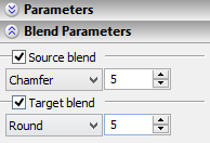
Blend parameters
If the resulting body is solid then it can be applied blend and chamfer options. Blending and chamfer creation can be done on the source and target surfaces independently. Source blend. Setting this attribute defines the mode of edge blending on the original surface, that is the surface on the side of the start section. Blending is done in the way of "Round" or "Chamfer". The parameter of the blend is defined in the next box. Target blend. Setting this attribute defines the mode of edge blending on the target surface, that is the surface on the side of the end section. Blending is done in the way of "Round" or "Chamfer". The parameter of the blend is defined in the next box. |
|