Paths |
  
|
Paths |
|
A path is a construction line passing through a sequence of nodes. The segments between the nodes can be straight lines or a portion of a construction entity between two given nodes. The following construction entities can be used: lines, circles, ellipses, splines and other paths.
Constructing 2D paths
The command "PA: Construct Path" is provided for constructing a 2D path.
The command is called by:
Icon |
Ribbon |
|---|---|
|
Draw → Construct → Path |
Keyboard |
Textual Menu |
<PA> |
Construct > Path |
The following actions become accessible upon entering the command:
![]() <Enter> Select a node or create a node at the nearest construction line intersection
<Enter> Select a node or create a node at the nearest construction line intersection
|
<Ctrl><F> |
Free mode on/off toggle |
|
<P> |
Set selected Element(s) Parameters |
|
<N> |
Select Node |
|
<L> |
Select Line |
|
<C> |
Select Circle |
|
<E> |
Select Ellipse |
|
<S> |
Select Spline |
|
<F4> |
Execute Edit Construction command |
|
<Esc> |
Exit command |
The 2D path creation procedure consists of selecting 2D nodes forming a sequence. After selecting the start node, you can select a construction line that connects this and the next node. Both nodes must belong to this construction line.
The step-by-step process is as follows:
1. Select the start node;
2. Select a construction line connecting the start node with the end node (optional);
3. Select the end node.
Selecting the start node of the path as the end node completes the path creation.
4. Confirm path creation or repeat the step 2. The end node selected in the step 3, becomes the start node for the next segment of the path.
Upon selecting the start node and the first segment, you can do the following:
![]() <Space> Select Graphic line
<Space> Select Graphic line
This option allows defining a path contour along graphic lines. Keep in mind that this approach can only be used when the path segments coincide with the graphic lines. In the case of multiple selection choices, the cursor should be pointing to the desired graphic line when using the <Space> option.
To speed up the process, one can use the option:
![]() <A> Find contour automatically
<A> Find contour automatically
This option will search for the next path segment automatically until the contour is closed (in the case of the closed path) or until reaches a dubious situation (when the path is ending or forking).
In both cases (when using the option <Space>, and upon automatic selection of the contour with the help of |
|
One can define a path using the same operations as in graphic line creation. In other words, one needs to define a sequence of path segment lines each having the start and the end node. To define the start or the end of a path segment line, select existing nodes (the key <N>) or create new ones (the key <Enter>) at intersections of construction line pairs.
As in the case of graphic entity creation, an arc is defined by first selecting a node, and then the construction circle by typing <C>.
Otherwise, a straight line will be created between the two nodes as the path segment instead of the arc. Including an elliptical arc or a spline or other curve segment in a path is similar to creating a circular arc.
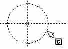
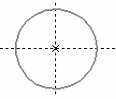
To define a path represented by a full circle, then without selecting any nodes point the cursor to the circle and type <С>. One can also construct a path from an ellipse, spline or other curve by using the options <E> and <S>, respectively.
In complex cases, when more than two construction lines intersect in one point, resulting in multiple overlapping nodes, the ending nodes of the path segments should be specified by selecting the intersecting line pairs hosting the desired node. This is done by using the keys <L>, <C>, <E>, <S>, standing for the respective types of construction entities.
In the cases when more than two construction lines intersect in one point but no nodes are created, the recommended technique is to create all necessary nodes by the command "N: Construct Node". In this way, specify the exact lines whose intersections yield nodes. After that, the path segments can be input using the <N> option.
To reject the last input path segment line, use the option
![]() <BackSpace> Delete last Contour segment
<BackSpace> Delete last Contour segment
All three above-mentioned techniques can be combined when defining a path.
If the end node of a closed path coincides with the start node, then the contour automatically closes and dehighlights, and an arrow is displayed in the end node indicating the direction of the defined path. This signals that the path has been completed.
A path can also be closed by using the option
![]() <Home> Close Contour
<Home> Close Contour
To complete definition of an open path, upon defining all segments use the option
![]() <Ctrl+Enter> Finish input
<Ctrl+Enter> Finish input
To cancel an action of path input, use the option
![]() <Esc> Cancel selection
<Esc> Cancel selection
Whenever two or more path segments are input in the command "PA: Construct Path", the right-click ![]() brings up the Right button action dialog box (this overrides the system settings).
brings up the Right button action dialog box (this overrides the system settings).
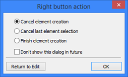
In this dialog box one can: "Cancel element creation", which is equivalent to <Esc> option; "Cancel last element selection", which is equivalent to <BackSpace> option; "Finish element creation", which is equivalent to <End> option. One can also set the flag "Don't show this dialog in future". In this case, the dialog box will not come back again, and the right-click ![]() action will be the one set last together with the "Don't show this dialog in future" flag, per the system settings.
action will be the one set last together with the "Don't show this dialog in future" flag, per the system settings.
The button [Return to Edit] brings the user back to 2D path creation mode.
Note that the same dialog is used in the "H: Create Hatch" command. A default ![]() action setting made in this dialog box in one of these commands will work in both commands. The selected option will be used in all newly opened documents until the end of the application session. To change the setting, close and reopen the application.
action setting made in this dialog box in one of these commands will work in both commands. The selected option will be used in all newly opened documents until the end of the application session. To change the setting, close and reopen the application.
If the dialog box does not pop up upon ![]() while in the command being described, and some action is performed instead, then a default
while in the command being described, and some action is performed instead, then a default ![]() action was already assigned earlier in the session within this command or in "H: Create Hatch".
action was already assigned earlier in the session within this command or in "H: Create Hatch".
2D path parameters
2D path parameters can be defined at during its editing. The 2D path parameters dialog box is called by the option
![]() <P> Set path parameters
<P> Set path parameters
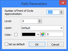
Number of Point for Circle Approximation. This parameter defines the accuracy of drawings of circles and circular arcs that are components of 2D paths.
Level. Places the path being created on a certain visibility level used for hiding some elements from display as necessary.
Layer. This parameter assigns the path being created to a certain layer.
Color. This parameter defines the color used for the path display.
Set as default. Turning on this flag means the current dialog parameter settings will be used in future for constructing new construction lines.
Editing 2D paths
By editing a path, one can add or delete nodes, select a different construction line to connect the end nodes of a particular path segment, as well as define new parameters.
Editing is done in the command "EC: Edit Construction".
Icon |
Ribbon |
|---|---|
|
Draw → Additional → 2D Construction |
Keyboard |
Textual Menu |
<EC> |
Edit > 2D Construction |
A path can be selected by pointing the cursor and clicking ![]() , or by the option:
, or by the option:
![]() <S> Select Spline
<S> Select Spline
As a result, the selected path gets highlighted, and its nodes marked.
Editing the type of a particular path segment
To modify the type of a particular path segment, do the following steps:
● Select a path;
● Using the mouse, select the path segment whose type needs to be modified;
● Select a construction entity defining the new type of the path segment: line, circle, ellipse and spline (including other 2D paths). Selection of a construction entity is done using the appropriate option. The end nodes of the path segment being edited must belong to the selected construction entities;
● Exit the particular path segment editing mode by right-clicking ![]() or pressing <Esc> on the keyboard.
or pressing <Esc> on the keyboard.
● Confirm changes by the option:
![]() <Ctrl+Enter> Finish input
<Ctrl+Enter> Finish input
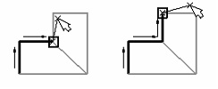
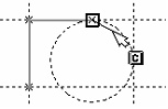
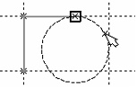
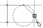
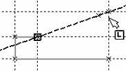
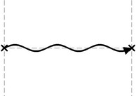
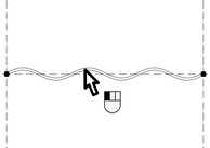
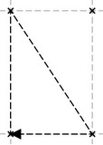
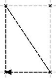
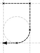
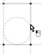
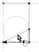
Let's review an example explaining the process of editing a particular segment of a path contour. The diagram shows the original path. The wave segment is to be replaced by a straight line. Call the command "EC: Edit Construction" and select the path. The next diagram shows the situation after selecting the path.
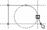
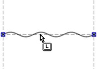
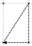
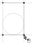
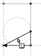
The contour is highlighted, and the end nodes are marked by small boxes. Move the cursor over the contour segment to be edited (the wave line in this case) and click ![]() . The selected contour segment will be highlighted and its nodes marked with larger boxes. This state is shown on the next diagram.
. The selected contour segment will be highlighted and its nodes marked with larger boxes. This state is shown on the next diagram.
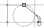
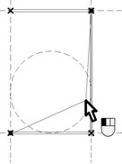
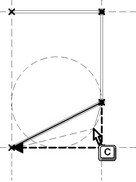
Select the straight line passing through the edited contour nodes by moving the cursor over and typing <L> key. The edited path segment now assumes the desired shape. The system still remains in the selected path segment editing mode. If transforming this segment is over, quit the current segment editing mode by right clicking ![]() or pressing <Esc> on the keyboard.
or pressing <Esc> on the keyboard.
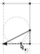
The icon ![]() becomes then accessible in the automenu. If there are no more modifications to the path, push
becomes then accessible in the automenu. If there are no more modifications to the path, push ![]() or <End> key. What is left is just changing the graphic line type, if necessary.
or <End> key. What is left is just changing the graphic line type, if necessary.
Similarly, one can replace a path segment with a circular or elliptic arc, or a spline segment, or a part of another path, if the circle, ellipse, spline or path is constructed based on the marked nodes. Simply use the appropriate option among <C>, <E> and <S>. If the new path segment was not created based on the marked nodes yet passes through them, then editing such path segment can be done using the option "Switch to 'Insert Point' mode" (the icon ![]() or the <I> key). This option will be fully described below.
or the <I> key). This option will be fully described below.
The selected segment of the path between two nodes can be replaced as many times as necessary. The path segment will stay selected until the user quits by right clicking ![]() or pressing <Esc>. If a contour segment was modified using the option "Switch to 'Insert Point' mode" (the icon
or pressing <Esc>. If a contour segment was modified using the option "Switch to 'Insert Point' mode" (the icon ![]() or <I> key), then the selected contour segment gets unselected after the change (no need to press <Esc>). Meanwhile, the system will remain in the path contour editing mode until the confirmation by
or <I> key), then the selected contour segment gets unselected after the change (no need to press <Esc>). Meanwhile, the system will remain in the path contour editing mode until the confirmation by ![]() or <End> key.
or <End> key.
Deleting a node inside path contour
To delete a node inside a path contour, do the following steps: Select a path (point at by the graphic cursor and click ![]() );
);
Select the path segment the node belongs to (point at by the graphic cursor and click ![]() );
);
Select the node to delete (point at by the graphic cursor and click ![]() );
);
Delete the selected node (the icon ![]() or the <Del> key);
or the <Del> key);
Confirm changes (the icon ![]() or the <End> key).
or the <End> key).
As a result, the new path segment passes through the two neighboring nodes.
Modifying a node position within path contour
To modify position of a node within a path, do the following steps: Select a path (point at by the graphic cursor and click ![]() );
);
Select the path segment the node belongs to (point at by the graphic cursor and click ![]() );
);
Select the node to move (point at by the graphic cursor and click ![]() );
);
Move the node to the desired position (the segments connecting the node to neighbors will rubberband as the node is moved);
Fix the node (point the cursor at an intersection of construction lines and click ![]() , or type <N> in the case of using an existing node).
, or type <N> in the case of using an existing node).
Confirm changes (the icon ![]() or the <End> key).
or the <End> key).
As a result of moving, the node will be connected with the neighbors by straight line segments, regardless of the former types of connecting entities).
Creation of additional nodes on a path contour
To create additional nodes on a path contour, do the following steps:
● Select a path (point at by the graphic cursor and click ![]() );
);
● Select the contour segment to split by new node(s) (point at by the graphic cursor and click ![]() );
);
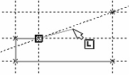
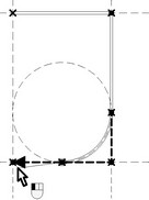
● Turn on the point insertion mode (the icon ![]() or the <I> key), and click on a contour segment. The segment becomes split in two, with the new node between them. The node and the segments rubberband with the cursor, the solid line segment connecting to the previous node and the dashed line to the next one. The order of the nodes after the insertion will be determined by the system automatically, depending on the path contour direction. Do not click on a segment near a vertex, as, instead of adding a node, this will start moving the existing node;
or the <I> key), and click on a contour segment. The segment becomes split in two, with the new node between them. The node and the segments rubberband with the cursor, the solid line segment connecting to the previous node and the dashed line to the next one. The order of the nodes after the insertion will be determined by the system automatically, depending on the path contour direction. Do not click on a segment near a vertex, as, instead of adding a node, this will start moving the existing node;
● Close the contour between the newly created node and the successive one. A shortcoming of the functionality is unavailability of the option "select graphic line";
● Contour input is complete once the closing node is selected, or the icon ![]() or the <End> key is pressed.
or the <End> key is pressed.
The system returns to the mode "Contour selected for editing". One can do other modifications, and then confirm all changes.
● Confirm changes (the icon ![]() or the <End> key).
or the <End> key).
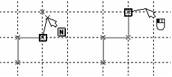
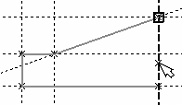
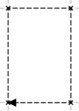
Let us illustrate the above with a specific example. Suppose, a path contour is to be modified as shown on the diagrams. To get the result, begin with calling the command "EC: Edit Construction". Then, using the option "Select Spline" (the icon ![]() , or the <S> key), select the path contour to be modified. Now, to get the result, perform the steps shown on the following diagrams.
, or the <S> key), select the path contour to be modified. Now, to get the result, perform the steps shown on the following diagrams.
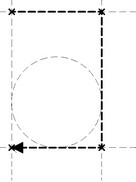
What is left is to press twice the ![]() icon or <End> key, and the contour editing task is complete. Then, adjust the graphic lines accordingly, if necessary.
icon or <End> key, and the contour editing task is complete. Then, adjust the graphic lines accordingly, if necessary.
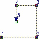
Displaying the contour point numbers
To toggle the display of the contour point numbers of a 2D path, use the option:
![]() <Q> Show/Hide contour point numbers
<Q> Show/Hide contour point numbers
With the option turned on, the points in the path are enumerated based on their position in the path and the path direction. A point number is displayed next to the respective node. When several subsequent points of a contour coincide, their numbers are displayed next to each other, separated by commas.