Profiles |
  
|
Profiles |
|
When a part being designed is intended for further processing, which might involve use of CNC centers and creation of numerical control procedures, or for certain other purposes, then the information about the part profile geometry can be saved to a file.
A profile is defined in the commands that create and edit hatches. To designate a hatch as a profile, you would need to set the parameter "Profile" in the hatch properties dialog. If, at the same time, there is no need to fill inside of the profile contour with hatching, then you can designate it as an invisible hatch by selecting the filling method "Invisible".

Profile parameters are output to a file by the command "PR: Write Profile":
Keyboard |
Textual menu |
Icon |
<PR> |
«Tools|Special Data|Profile» |
|
After calling the command, select the hatch profile by clicking ![]() . If the drawing contains a single profile, then it will be selected automatically upon calling the command. The command parameters dialog window appears after selecting the profile.
. If the drawing contains a single profile, then it will be selected automatically upon calling the command. The command parameters dialog window appears after selecting the profile.
In this dialog window, first of all you need to select which profile parameters are to write to file:
Properties. This saves information about the profile in one of the selected formats (AutoCAD DXF, AutoCAD DWG, Dragon, EIA);
Geometry. This outputs on the screen or to a file the profile geometrical characteristics (area, perimeter, moments of inertia, etc.).
The "Output Path:" parameter defines the name and the path to the file, in which the profile information will be saved. The file extension will be set automatically, based on the selected parameters and output format. To browse for the file, you can use the button ![]() .
.
If the general profile properties are selected, then the parameter "Output format" allows selecting the desired file format from the list:

AutoCAD DXF (*.dxf). The profile information will be written in the DXF format of AutoCAD system.
AutoCAD DWG (*.dwg). The profile information will be written in the DWG format of AutoCAD system.
DRAGON (*.drg). The profile information will be written in the DRAGON system format.
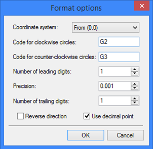
EIA (*.eia). For this format, you can specify the format options by clicking the button [Options…]. The EIA format parameters dialog window will appear on the screen:
Coordinate system. Defines the point, with respect to which the profile coordinates will be counted. You can select from the list: "From (0,0)", "From contour beginning", "Incremental". Code for clockwise circles. Sets the code for identifying arcs defined as clockwise.
Code for counter-clockwise circles. Sets the code for identifying arcs defined as counter-clockwise.
Number of leading digits. Sets the mandatory number of digits before the decimal point when writing numbers to a file.
Precision. Sets the rounding precision for writing numbers to a file.
Number of trailing digits. Sets the mandatory number of digits after the decimal point.
Reverse direction. This lets you get coordinates of the profile in the direction opposite to the specified one.
Use decimal point. This parameter is required for defining a fixed format without the decimal point.
Upon clicking [OK], the profile information will written to the file in the selected format.
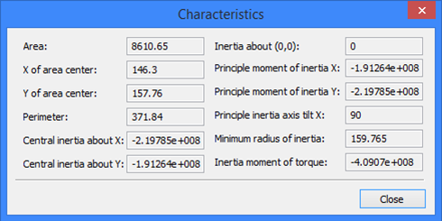
Upon selecting "Geometry" option, the "Geometry" group of parameters becomes accessible. Then, you need to select the necessary geometrical characteristics of the profile: General characteristics or Moment about axis. Upon clicking [OK], the selected characteristics will be displayed in the dialog window. Additionally, if the "Write to file" flag is set, the characteristics will also be saved in an external file "*.pro", defined by the parameter "Output Path".
General characteristics include the following profile properties:
Area and perimeter of the profile;
X and Y of area center of the profile;
Central inertia about X and Y;
Inertia about (0,0);
Principal moment of inertia X and Y;
Principal inertia axis tilt X - the tilt of the principal axis of inertia with respect to the X axis;
Minimum radius of inertia;
Inertia moment of torque.
When selecting a moment of inertia about an axis for examination, after clicking [OK] in the command's parameters dialog, you need to additionally specify the straight line, about which the moment will be calculated. At that time, the following option will be available in the automenu:
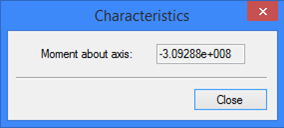
![]() <L> Select Line
<L> Select Line
After selecting the axis, the dialog window will display the calculated moment.