Section View |
  
|
Section View |
|
The section view, arrow view and local area view are necessary detailing elements of a drawing. T-FLEX CAD system provides full range of functionalities for satisfying this requirement.
Creating section view
The command for section view creation, "SE: Create Section" can be called as follows:
Icon |
Ribbon |
|---|---|
|
Draw → Title Block → Section |
Keyboard |
Textual Menu |
<SE> |
Draw > Section |
Upon calling the command, you will get access to the following set of options:
![]() <P> Set Section Line Parameters
<P> Set Section Line Parameters
![]() <Alt+P> Copy Properties from Existing Element
<Alt+P> Copy Properties from Existing Element
![]() <S> Create two point Section
<S> Create two point Section
![]() <D> Create multiple point section
<D> Create multiple point section
![]() <R> Create Arrow View
<R> Create Arrow View
![]() <V> Create View
<V> Create View
![]() <N> Select Attachment Node
<N> Select Attachment Node
![]() <Z> Change View Direction
<Z> Change View Direction
![]() <F4> Execute Edit command
<F4> Execute Edit command
![]() <Esc> Exit command
<Esc> Exit command
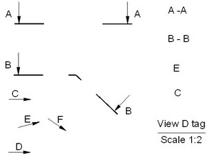
Next, select the type of the section view to create: a simple (two-point) section, a multiple-point section, an arrow view or a view notation.
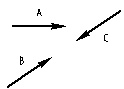
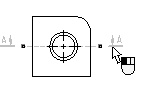
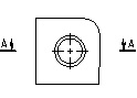
Two-point section
Two-point section creation begins with selecting two attachment points. Those can be defined either in the absolute coordinates or snapped to 2D nodes. Move the pointer to the desired position and click ![]() . As the pointer approaches 2D nodes, the object snapping activates, highlighting the nodes. Assign the second attachment point similarly. The preview of the element being created updates dynamically with your manipulations. Next (refer to the third diagram from the left), you need to define the offset of the view notation arrows from the attachment points. Do this by positioning the pointer appropriately. To fix the position, click
. As the pointer approaches 2D nodes, the object snapping activates, highlighting the nodes. Assign the second attachment point similarly. The preview of the element being created updates dynamically with your manipulations. Next (refer to the third diagram from the left), you need to define the offset of the view notation arrows from the attachment points. Do this by positioning the pointer appropriately. To fix the position, click ![]() . The result is shown on the right-most diagram.
. The result is shown on the right-most diagram.
Arrow offset with respect to a fixing nodes can be skipped by pressing ![]() in the automenu or in the properties window.
in the automenu or in the properties window.
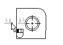
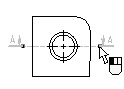
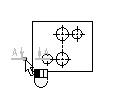
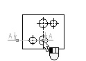
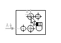
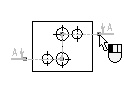
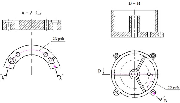
Multiple-point section
The multiple-point section creation is similar to creating a two-point section. The difference is in the number of the attachment points to select, which is unlimited in the case of a multiple-point section. To call the command for creating a multiple-point section, press the automenu icon ![]() or type the key <D>. The sequence of actions for creating a multiple-point section is shown on the following diagrams.
or type the key <D>. The sequence of actions for creating a multiple-point section is shown on the following diagrams.
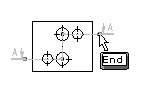
Upon entering the desired number of points, you need to press the automenu icon ![]() or the key <End>.
or the key <End>.
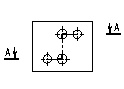
Instead of specifying the individual points of the section, it is possible to select an existing 2D path with the help of the option:
|
<T> |
Select 2D path |
The created section will repeat the form of the selected path.
The view direction can be flipped to the opposite at any time by pressing the automenu icon ![]() or the key <Z>.
or the key <Z>.
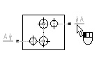
After defining all fixing points of section, you must specify the offset of arrow regarding fixing points with ![]() . The offset definition may be omitted by pressing
. The offset definition may be omitted by pressing ![]() in automenu or in the properties window.
in automenu or in the properties window.
Section Properties
Section parameters can be set at any time prior to the completion of element creation in the properties window of the command.
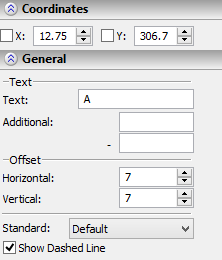
The first sub-dialog "Coordinates" contains fields for entering precise coordinates of section fixing points. Current coordinates are dynamically traced on moving the cursor in the drawing window.
"General" sub-dialog allows you to set all the basic parameters of section. These settings include:
The group "Text": Text. The text to be displayed next to the arrows. This entry is filled automatically with a subsequent letter of the alphabet, beginning with the letter "A". If the number of notations exceeds the number of letters in the alphabet, the multiple-letter combinations are used: AA, AB, AC, …, AAAAAAA, etc. If necessary, you can manually type a text string of an arbitrary length in this input box. Additional. The input boxes of this parameter allow entering different text for each arrow. The specified text strings will be displayed next to the text defined by the previous parameter. |
|
The group “Offset”
Horizontal. Defines the text offset from the arrow in the outward direction along the leader, in the model measurement units.
Vertical. The text offset from the leader.
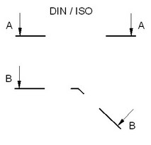
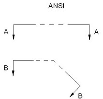
Standard. Defines the view notation standard. You can choose from the three options: the ISO standard, the ANSI standard and "Default".
In the case of using the last option, the standard is defined by the "Standard/Dimension" parameter setting in the command "ST: Set Document Parameters", the tab "Dimensions". The ANSI standard permits displaying the dashed line (the parameter "Show Dashed Line").
Section Dimensions
The group "Lines":
Length. Defines the length of the leader.
Line Width. Defines the thickness of the leader. In the case of using the "Default" setting, this parameter value is calculated based on the "Line thickness/Thick lines" parameter setting in the command "ST: Set Document Parameters" (the tab "Lines").
Offset on Start. The offset of the leader from the first node of the view notation.
Offset on End. The offset of the leader from the last node of the view notation.
Dash Length. Sets the length of the medium dashed strokes (displayable only in ANSI standard).
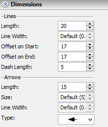
The group "Arrows":
Length. Sets the arrow length of the view direction notation.
Size. Sets the size of the view direction arrow. In the case of using the "Default" setting, this parameter value is calculated based on the "Arrow (end) size" parameter setting in the command "ST: Set Document Parameters" (the tab "Lines").
Line Width. Sets the line thickness of the view direction arrow. In the case of using the "Default" setting, this parameter value is calculated based on the "Line thickness/Thick lines" parameter setting in the command "ST: Set Document Parameters" (the tab "Lines").
Type. Sets the type of the view direction arrow.
The parameters on this tab are defined in the measurement units set in the drawing parameters (the command "ST: Set Document Parameters").
Section parameters can be also set in the section Parameters dialog box, opened by option ![]() . In this dialog, in addition to the above section properties, you can specify system-wide settings: Color, Level, Priority, Layer and [Font]. They are entered the same way as in other elements.
. In this dialog, in addition to the above section properties, you can specify system-wide settings: Color, Level, Priority, Layer and [Font]. They are entered the same way as in other elements.
You should note that the size of the view designation text is associated with the font size that is specified in the parameters of a particular element, or in command "ST: Set Document Parameters " on the "Font" tab.
Copying Parameters from Existing Notations of Section
The values of parameters of the notation of the section being created can be quickly copied from an already existing notation of the section. To do so, it is necessary to use the option:
|
<Alt+P> |
Copy Properties from Existing Element |
This option is available in the automenu of the command before creation of the view notation or during the process of creation.
After this option is invoked, it is sufficient to indicate the notation of the section whose parameters' values must be transferred to the element being created.
To assign the copied values of the parameters to all new notations of the section, it is required to activate the additional option before selection of the original element:
|
<S> |
Set Properties as Default |
When the option is activated, the copied parameters will be saved as default parameters.
This option simplifies creation of the notations of a section with identical parameters. However, it does not allow us to copy individual parameters or parameters from an object of another type. In such cases it is more convenient to use the general mechanism of editing parameters of elements in the properties window.
Arrow view
An arrow view can be attached to a node, defined by assigning the view direction vector by two nodes, or positioned in the absolute coordinates without attachment to any drawing objects. To create an arrow view, press the automenu icon |
|
![]() <B> Set First Attachment Point.
<B> Set First Attachment Point.
![]() <E> Set Second Attachment Point.
<E> Set Second Attachment Point.
![]() <Z> Change View Direction.
<Z> Change View Direction.
![]() <H> Change Text Placement.
<H> Change Text Placement.
For attachment in the absolute coordinates, you can simply click ![]() . The view notation will then fix at the current pointer position.
. The view notation will then fix at the current pointer position.
For attachment to a 2D node, you need to use the option <N> (the automenu icon ![]() ) or rely on the object snapping. As the pointer approaches a 2D node or a line intersection, the respective entities are highlighted. You can then click
) or rely on the object snapping. As the pointer approaches a 2D node or a line intersection, the respective entities are highlighted. You can then click ![]() .
.
By default, the arrow is positioned horizontally and directed from left to right. The arrow direction can be quickly rotated by the angle multiple of 90° by pressing the automenu icon ![]() or the key <Z>.
or the key <Z>.
For attachment to two nodes, subsequently use the automenu options:
![]() <B> Set First Attachment Point.
<B> Set First Attachment Point.
![]() <E> Set Second Attachment Point.
<E> Set Second Attachment Point.
and consequently select two 2D nodes.
You can change the text position with respect to the arrow line at any time by using the option ![]() or the key <H>.
or the key <H>.
Coordinates. The input boxes for specifying the exact X and Y coordinates when positioning the view notation in the absolute coordinates.
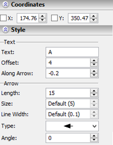
The group "Text".
Text. The text entered in this box will be displayed next to the arrow. By default, this entry is filled with letters in the alphabetical order, starting with the letter "A". You can manually input a text string of arbitrary length.
Offset. Sets the text offset from the arrow.
Along Arrow. Sets text offset along arrow.
The group "Arrow".
Length. Sets the length of the view direction arrow.
Size. Sets the size of the view direction arrow. In the case of using the “Default” setting, this parameter value is calculated based on the “Arrow (end) size” parameter setting in the command “ST: Set Document Parameters” (the tab “Lines”).
Line Width. Sets the line thickness of the view direction arrow. In the case of using the “Default” setting, this parameter value is calculated based on the “Line thickness/Thick lines” parameter setting in the command “ST: Set Document Parameters” (the tab “Lines”).
Type. Defines the type of the view direction arrow.
Angle. Angle of arrow rotation that will define the view direction.
The group "Placement"
Provides the respective fields for entering X and Y coordinate values defining the element position. You can also specify the arrow rotation angle that will determine the view direction.
Color, Level, Priority, Layer and [Font] are defined in the same way as in other T-FLEX elements.
The ![]() option allows us to copy parameters from another already existing arrow view.
option allows us to copy parameters from another already existing arrow view.
View notation
To create a view notation, press the automenu icon ![]() or the key <V>.
or the key <V>.
A view notation starts rubberbanding on the screen. Move the pointer to the desired position on the drawing and click ![]() to fix the element. In this way, the view notation will be positioned in the absolute coordinates that can be entered exactly in the "View Properties" dialog box (see below).
to fix the element. In this way, the view notation will be positioned in the absolute coordinates that can be entered exactly in the "View Properties" dialog box (see below).
For attachment to a 2D node, you need to use the option <N> (the automenu icon ![]() ) or rely on the object snapping. As the pointer approaches a 2D node or a line intersection, the respective entities are highlighted. You can then click
) or rely on the object snapping. As the pointer approaches a 2D node or a line intersection, the respective entities are highlighted. You can then click ![]() .
.
The default text is automatically created next to the leader of the view notation. The first such created element is labeled "A-A", the subsequent ones – the respective letters in the alphabetical order, as "B-B", etc.
You can copy the text from an existing section or arrow view. To do this, press the automenu icon ![]() or the key <C>. Next, select by the mouse the desired arrow view notation or section.
or the key <C>. Next, select by the mouse the desired arrow view notation or section.
Coordinates. The input boxes for specifying the exact X and Y coordinates when positioning the view notation in the absolute coordinates.
The group "Style"
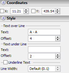
Text over Line. The text string is positioned above the leader. You can manually input a string of an arbitrary length.
Offset. The distance from the leader to the text above it.
Text under Line. The text string is positioned below the leader. You can manually input a string of an arbitrary length. Not displayed by default.
Offset. The distance from the leader to the text below it.
Underline Text. This flag will underline text of the view notation.
Line Width. Sets the width of the dividing leader line.
The ![]() option allows us to copy parameters with another already existing view notation.
option allows us to copy parameters with another already existing view notation.
Editing view notation
The attachment, notation position and parameter values of a view can be modified by the command "ESE: Edit Section" (the option <F4> in the command "SE: Create Section View"):
Keyboard |
Textual Menu |
Icon |
<ESE> |
"Edit|Draw|Section" |
|
Upon calling the command, the following icons become available in the automenu:
![]() <*> Select All Elements
<*> Select All Elements
![]() <Esc> Exit command
<Esc> Exit command
A view can be selected by pointing the mouse to it and clicking ![]() , or by multiple selections. As in the case of other drawing elements, multiple selections are done by the option
, or by multiple selections. As in the case of other drawing elements, multiple selections are done by the option ![]() . Using
. Using ![]() while holding down the key <Shift> adds an element to the list of selected, while with the key <Ctrl> - excludes from the list of selected.
while holding down the key <Shift> adds an element to the list of selected, while with the key <Ctrl> - excludes from the list of selected.
In the case of multiple selections, you can use the options:
![]() <P> Properties (accessible only when same-type elements are selected)
<P> Properties (accessible only when same-type elements are selected)
![]() <Del> Delete selected element(s)
<Del> Delete selected element(s)
When a single element is selected, the set of the available options depends on the type of this element.