Splines |
  
|
Splines |
|
Main concepts
The construction spline entities allow creating various curves. Unlike the straight construction lines, the splines have finite length. In general, spline-handling techniques are not different from those used for other construction entities. Nodes are created at intersections and tangency points. Graphic entities and hatch contour segments can be constructed along splines. Spline selection is done in many commands using the <S> option (the same key is used for selecting other curves as well, such as functions, offset curves and paths). T-FLEX uses NURBS-type splines.
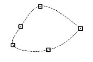
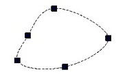
A spline is created based on a set of nodes that represent the defining points of the spline. Therefore, modification of the node positions will result in a change to the shape of the curve constructed based on these points.
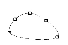
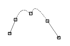
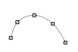
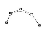
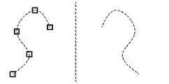
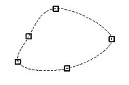
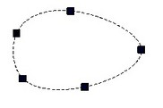
Splines belong to two main types: passing through the nodes directly and using the nodes as vertices of the control polygon.
There are also closed splines. |
|
End-point conditions can be defined for splines through points via tangency vectors that are constructed based on nodes as well. |
|
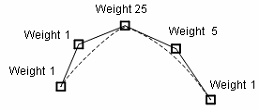
The control polygon nodes can be assigned weights. The more the node's weight, the closer the curve will pass to this node than to the neighboring ones. Vise versa, the lesser the weight, the smaller is the influence of the node on the curve shape. |
|
Splines appear on the drawings as polylines made of numerous straight segments. The number of segments and, therefore, the accuracy of the output can be controlled by specifying the number of tessellation segments between a pairs of neighboring defining nodes. Each section of the spline will be tessellated by this number of segments when output. The more segments are used, the higher quality and accuracy will be achieved in the image. However, a too high number of segments may cause delays in spline handling by the system.


Constructing splines
When creating spline, one can either use the existing nodes or automatically create new ones (free nodes or at construction line intersections).
Call the command "SP: Construct Spline":
Icon |
Ribbon |
|---|---|
|
Draw → Construct → Spline |
Keyboard |
Textual Menu |
<SP> |
Construct > Spline |
The following options become available to the user:
|
<Ctrl><F> |
Free mode on/off toggle |
|
<N> |
Select Node |
|
<P> |
Set Spline parameters. |
|
<T> |
Click to select tangent Node. |
|
<O> |
Create Spline in Polar Coordinate System |
|
<A> |
Select axis of symmetry (straight Line) |
|
<G> |
Select Graphic line |
|
<F4> |
Execute Edit Construction command |
|
<Esc> |
Exit command |
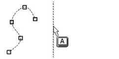
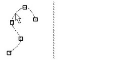
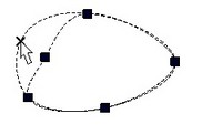
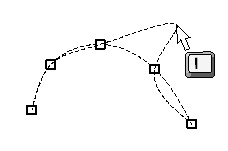
Upon entering spline creation command, the user can use ![]() or <N> in order to set the defining nodes of the spline. The curve being created will be rubberbanding on the screen. In the case of control polygon type splines, the polyline will be displayed along with the spline curve. Now, the option for finishing the spline input becomes available in the automenu that can be used for completing spline creation.
or <N> in order to set the defining nodes of the spline. The curve being created will be rubberbanding on the screen. In the case of control polygon type splines, the polyline will be displayed along with the spline curve. Now, the option for finishing the spline input becomes available in the automenu that can be used for completing spline creation.
![]() <End> Finish Spline input
<End> Finish Spline input
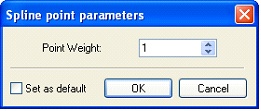
When creating a control polygon type spline, the weights of each particular point can be defined with the help of <P> option.
To define a spline with end-point tangency conditions, follow these steps:
Use the option ![]() to define start tangency direction.
to define start tangency direction.
Specify the desired sequence of nodes (two minimum).
Use the option ![]() and define the end tangency condition.
and define the end tangency condition.
To construct a spline in a polar coordinate system, use the option ![]() . This option allows creating a spline passing through two points with tangency directions defined there. To create such a spline, define a coordinate system, the start and end points of the spline and the tangent angles at the ends. The angles are defined in the polar coordinate system by the ratio of degrees to millimeters. This way of defining a construction entity may be used, for instance, in camshaft design.
. This option allows creating a spline passing through two points with tangency directions defined there. To create such a spline, define a coordinate system, the start and end points of the spline and the tangent angles at the ends. The angles are defined in the polar coordinate system by the ratio of degrees to millimeters. This way of defining a construction entity may be used, for instance, in camshaft design.
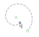
To create symmetrical splines, first engage the option ![]() and select the symmetry axis, and then select the desired spline.
and select the symmetry axis, and then select the desired spline.
Please note special issues in creation of closed splines. If the start point was selected as the end point as well, the spline will be closed yet not necessarily smooth at the start-to-end connection. To impose such smoothness, set "Closed" option in the parameters dialog box and do not connect the rubberbanded spline to the start point.
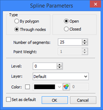
Spline parameters
The parameters of a spline created in a Cartesian coordinate system can be defined or modified via the Type. This parameter defines the spline type ("By polygon", "Through nodes"). The type can only be selected at creation time. Next stands the spline option – "Open" or "Closed". Number of segments defines the number of tessellation segments between two neighboring spline nodes on a plot. This parameter can be defined by a variable. Point weight. This item is used in creation of splines by control polygons. The weight parameter must be greater than zero. Level, layer and color are defined and used in the same way as in all the rest construction entities. |
|
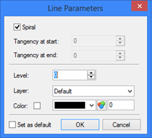
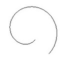
A different set of parameters is used for splines defined in polar coordinates, as follows: Spiral. With this flag set, a spiral is constructed with the center in the first point, start in the second point, and the end in the third point. Without this option, the following two parameters are used: Tangency at start. Tangency at end. Define the angles from horizontal of the tangencies in the spline end points. Level, layer and color are defined and used in the same way as in all the rest construction entities. |
|
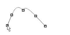
Editing splines
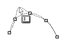
Editing splines includes changing spline shape, adding or deleting defining nodes and modifying various parameters. Spline editing is done in the command "EC: Edit Construction". Once a particular spline is selected for editing (by pointing to with the cursor and clicking ![]() ), then the spline curve will be highlighted together with the defining nodes.
), then the spline curve will be highlighted together with the defining nodes.
The following options become available in the automenu:
![]() <Enter> Select the nearest defining node of the spline to modify
<Enter> Select the nearest defining node of the spline to modify
![]() <P> Set costruction line parameters
<P> Set costruction line parameters
![]() <V> Mode of dynamic recalculation of model
<V> Mode of dynamic recalculation of model
![]() <Y> Create Name for selected Element
<Y> Create Name for selected Element
![]() <I> Selected Other Element
<I> Selected Other Element
![]() <Del> Delete selected Element(s)
<Del> Delete selected Element(s)
![]() <Esc> Cancel selection
<Esc> Cancel selection
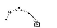
Once a defining node of the spline is selected by clicking ![]() , it can be reassigned by selecting another node, delete, or add a new one. Once a defining node is selected, the spline begins rubberbanding, following the cursor, just like at creation time. A following mouse click
, it can be reassigned by selecting another node, delete, or add a new one. Once a defining node is selected, the spline begins rubberbanding, following the cursor, just like at creation time. A following mouse click ![]() selects another node or creates a new one. For convenience, the old node gets deleted if it was not referenced by any other element.
selects another node or creates a new one. For convenience, the old node gets deleted if it was not referenced by any other element.
Note that the node position and, therefore, the shape of the curve, can be modified in the node editing command "EN: Edit Node".
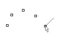
To add a new defining node use the option <I>.
![]() <I> Switch to "Insert Point" mode
<I> Switch to "Insert Point" mode
Note that the insertion of the new node will be before or after the selected node, depending on where the cursor was at the instant of option activation.
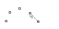
To fix the new node, click ![]() .
.