Creating Node by Two Projections |
  
|
Creating Node by Two Projections |
|
A 3D node can also be created based on its two projections on different workplanes. 2D nodes are used as projections.
To create a 3D node, specify two 2D nodes lying on different workplanes. To create a 3D node directly on a workplane, specify just one 2D node, that is, just one node projection. The workplane and the two node coordinates will define the position of the 3D node in space in this case. To define the height of the node being created above the workplane, the second projection needs to be specified, that is, the second 2D node. The two projections define a point in space unambiguously.
When defining a 3D node by one projection, one can use a 2D node lying on a worksurface. As a result, the 3D node is created lying on the given worksurface.
When defining a node by two projections, erroneous situations might occur. The projection is the point at the intersection of the workplane and the normal. The second projection is the second intersection. To define a point in space, the two normals must intersect. If two projections do not define a point in space, a relevant message is display in the diagnostics window. As a rule, errors occur when defining projections on two views that do not have an explicit projective relation.
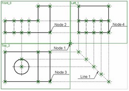
For instance, in the case shown on the diagram, one can select Node_2 is the first projection that belongs to the workplane "Front". For the second projection, one can select, for instance, Node_3. Two projections unambiguously define a point in space.
To create a 3D node in reviewed example, one can also use Node_3 on the plan view and Node_4 on the side view. To avoid erroneous situations, the drawings on these views have a projective relation, as defined by the projecting line Line_1.
The mode of creating a 3D node by two projections is launched via the automenu option:
![]() <J> Create 3D node by two projections
<J> Create 3D node by two projections
Upon calling the option, the command automenu subsequently brings the options for defining 2D node projections:
![]() <F> Set 3D node 1st projection
<F> Set 3D node 1st projection
![]() <G> Set 3D node 2nd projection
<G> Set 3D node 2nd projection
One can select a 2D node by clicking ![]() in the 2D window. The selected node is highlighted. Also highlighted is the workplane that contains the node by default (a workplane contains an element by default when the element appearance on the screen is within the workplane bounds). To select a different workplane, use the option:
in the 2D window. The selected node is highlighted. Also highlighted is the workplane that contains the node by default (a workplane contains an element by default when the element appearance on the screen is within the workplane bounds). To select a different workplane, use the option:
![]() <W> Select other workplane
<W> Select other workplane
To cancel use of the second projection (in the case when it is already defined), push the following automenu option:
![]() <D> Delete 2nd projection of 3D Node
<D> Delete 2nd projection of 3D Node
The absolute coordinates of the node being created are tracked in the property window.