Creating Node Based on Single Connected 3D Profile, 3D Path, or Edge |
  
|
Creating Node Based on Single Connected 3D Profile, 3D Path, or Edge |
|
Selection of a 3D profile (single connected only), 3D path or edge activates the mode of creating a node on the selected element. The selected element is highlighted. To create a node, upon selecting the parent element do the following:
- Select the origin point for defining the node position on the parent element;
- Specify the position of the node being created on the parent element by the offset distance from the reference point (along the parent element).
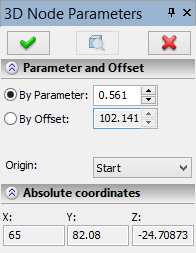
When the mode starts, the property window displays a dialog box for defining node parameters. The dialog has two sections. The section "Parameter and Offset" serves for defining the reference point and the node position on the parent element. The section "Absolute coordinates" displays the current absolute coordinates of the node being created. The origin point for positioning the node can be specified as: start, end, center of the parent element or an arbitrary 3D point. The start point of a 3D profile, path or edge can be distinguished from the end point by the kind of element highlighting: an arrow at one of the ends of the highlighted element indicates the end point. In the case of closed 3D elements, the positions of the start and end points coincide. |
|
In the case of using an arbitrary 3D point as the origin, two possibilities exist. If the selected point belongs to the parent element, then it will be used as the origin point. Otherwise, the reference point will be the nearest point on the parent element to this specified 3D point.
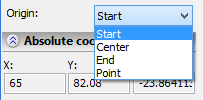
Selection of the origin point is done in the property window from the list under the "Origin" item. The pull down list of values contains the following options: "Start", "End", "Center", "Point". Before selecting the latter option, specify a 3D point to be used as the origin for defining the node position on the parent element. An additional option is provided in the automenu for selecting the point:
![]() <G> Set point for offset origin
<G> Set point for offset origin
Upon activating the option, one can select the desired 3D point right in the 3D scene. The 3D node used as the origin can also be selected in the 3D model tree.
To reject the selected point, use another additional option:
![]() <X> Cancel selection of offset origin
<X> Cancel selection of offset origin
The node position on the parent element can be defined either in the property window or directly in the 3D scene. When using the property window, first choose the way of defining the distance by setting the switch "By Parameter/By Offset" as desired:
- By Parameter. The distance from the origin point is set in the relative units (0 – the position of the origin, 1 – the distance equal of the length of the whole parent element). For example, if the midpoint of the profile/path is used as the origin, then parameter values can vary in the range [-0,5;0,5].
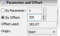
- By Offset. The distance from the origin is set in the model units.
Should the user enter the value of the offset greater than the length of the parent element, the node is constructed at its end. An additional field appears in the property window, "Offset used", that displays the actual distance from the origin point to the created 3D node. As the parameter or the offset is modified in the dialog box, the node in the 3D scene moves accordingly.
In the 3D scene, simply point the mouse cursor to the desired position of the node on the object and click ![]() . On subsequent clicks in the 3D scene, the node will move to the new position.
. On subsequent clicks in the 3D scene, the node will move to the new position.
At the beginning of node creation, its position coincides with the position of the mouse click selecting the parent 3D element.