Creating Node at Intersection of Elements |
  
|
Creating Node at Intersection of Elements |
|
A 3D node can be constructed at an intersection of two 3D elements: the first and the second. To construct a node, virtually any elements can be used: a path and a body, two paths, an edge and a body, etc. The pairs of 3D elements admissible for selection are defined solely by the possibility of getting an intersection between those resulting in a point. To exclude situations when the intersection of the specified elements is not a point, only a curve or a line are allowed as the first element, while the second element to intersect can be a curve, a line, a sheet body or a solid body.
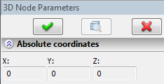
To create a node, specify the intersecting elements. The order of selecting the elements is not important. The second element to intersect can be selected ahead of the first one. Upon specifying both elements, the system defines the point of intersection for creating a node there. Meanwhile, the property window displays its absolute coordinates. If several intersection points exist, then the one is selected by default that was nearest to the element selecting clicks. A different intersection can be selected if necessary.
This mode is turned on by the option:
![]() <Q> Construct 3D Node on intersection of elements
<Q> Construct 3D Node on intersection of elements
Upon calling this option, the command switches into the mode of defining the first element. The automenu gets additional options:
![]() <W> Select curve as first element
<W> Select curve as first element
![]() <L> Select axis as first element
<L> Select axis as first element
These options allow selecting a curve or straight line to use as the first intersecting element. When selecting 3D elements for the line, pay attention to the state of the element selection filters of these options.
To reject the first selected element, use the option:
![]() <X> Cancel selection of first element
<X> Cancel selection of first element
To proceed with defining the second element, use the option:
![]() <T> Select second element
<T> Select second element
Upon defining the first element, the command automatically switches to the mode of defining the second element.
The following options are used in the mode of defining the second element:
![]() <W> Select curve as second element
<W> Select curve as second element
![]() <L> Select axis as second element
<L> Select axis as second element
![]() <F> Select surface as second element
<F> Select surface as second element
![]() <E> Select sheet body as second element
<E> Select sheet body as second element
![]() <B> Select body as second element
<B> Select body as second element
As appears from option names, those allow selecting a curve, straight line, plane, surface, solid body, or sheet body as the second intersecting element. When selecting 3D elements defining a line, surface, or body, the element selection filters are used.
To reject selection of the second element, use the option:
![]() <X> Cancel selection of second element
<X> Cancel selection of second element
To return to the mode of specifying the first element, use the option:
![]() <T> Select first element
<T> Select first element
If selected elements have multiple intersections, use the following option to select the desired one:
![]() <N> Select another intersection
<N> Select another intersection