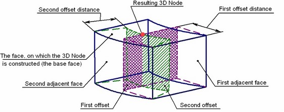
Creating a 3D node by faces and offsets from a solid is a special case of creating a node on a face. In this mode, first specify the base face for the node to be placed on. The required node position on this face is defined using two additional faces of the same body, adjacent to the base face (having a common edge), and their offsets. To create the node, offsets are constructed from the additional faces at the specified distances. The node is defined as the intersection point of the base face and the offsets.
All three faces can have the underlying surface of any type (a plane, torus, sphere, cone, spline surface). Alternatively, the additional faces can be selected by selecting the edges that join the faces with the base face.
In this mode, 3D node construction is done as follows:
- The offsets from the additional faces are constructed. The offset distances are defined by the values entered for those faces. In the case of a positive distance, the offset is constructed inside the body, negative - outside.
- An intersection of the base face and the offsets of the additional faces are calculated. The resulting intersection will be the point of the 3D node creation.
In simple cases, the face surfaces can be extended beyond the bounds (both the base and the offsets). For a plane and cone, this extension is unlimited, while for a torus or a sphere it is closed. This allows, for example, creating a node beyond the bounds of the base face, yet lying on its underlying surface (when the offset distance is negative). This also allows constructing 3D nodes in the situations when the offsets from the additional side faces do not intersect with the base face.

The mode of creating a 3D node by faces and offsets is invoked via the following automenu option provided in the command:
![]() <O> Construct 3D Node using faces and offsets
<O> Construct 3D Node using faces and offsets
Upon starting this mode, additional options for selecting faces appear in the automenu. Select the base face using the following option:
![]() <F> Select face containing 3D node
<F> Select face containing 3D node
Was selected face is highlighted in green (by default). A set of options for selecting additional faces or their defining edges becomes available in the automenu:
![]() <E> Select Edge that sets the first offset
<E> Select Edge that sets the first offset
![]() <T> Select Face that sets the first offset
<T> Select Face that sets the first offset
![]() <D> Select Edge that sets the second offset
<D> Select Edge that sets the second offset
![]() <G> Select Face that sets the second offset
<G> Select Face that sets the second offset
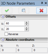
The values of the offset distances from the side faces that define the position on the 3D node being created, are entered in the property window, in the section "Offsets". Setting the additional flag "Reverse" flips the direction of counting the offset distances. The node position on the base face would correspond to the negative values of the offsets. When the flag is cleared, the positive offsets are inside the body, meaning that the node is created within the face. The desired node position on the base face can be directly specified in the 3D scene by clicking ![]() . Meanwhile, the property window will display the corresponding values of the offsets.
. Meanwhile, the property window will display the corresponding values of the offsets.
