Creating Workplane Parallel to Geometrical Plane |
  
|
Creating Workplane Parallel to Geometrical Plane |
|
To create a workplane parallel to an arbitrary geometrical plane, use the following option of the command automenu:
![]() <1> Select Plane that defines Workplane position
<1> Select Plane that defines Workplane position
The set of filters for this option allows selecting a 3D element in the 3D scene, defining the desired geometrical plane. This can be another workplane, a flat face (the face underlying plane is actually used), a flat elliptical edge, LCS (one of its principal planes), etc.
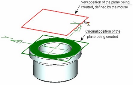
Upon selecting the 3D element in the 3D scene, the new workplane is displayed. The original position of the created plane coincides with the position of the geometrical plane defined by the parent 3D element. Exception is the case of creating a workplane based on another workplane – in such a case, a small initial offset is used by default. The final position of the plane being created can be defined by entering a numerical value of the offset from the original 3D element in the command property window. Alternatively, the offset can be defined directly in the 3D scene, using the mouse. For this, you need to move the pointer to the displayed image of the plane being created (the pointer will change to ![]() ), depress
), depress ![]() and, while holding down the left mouse button, move the plane to the desired position.
and, while holding down the left mouse button, move the plane to the desired position.
One can also specify an additional 3D element to define the workplane position. To define the position of the plane being created by using additional 3D elements, the following options are used:
![]() <3> Select first Point of Workplane position
<3> Select first Point of Workplane position
![]() <5> Select Surface to which Workplane is tangent
<5> Select Surface to which Workplane is tangent
![]() <7> Select Edge to which Workplane is tangent
<7> Select Edge to which Workplane is tangent
The workplane will be oriented parallel to the original 3D element (or, rather, the geometrical plane defined by this element) and pass either through the specified 3D point or tangent to the face (or, rather, to its underlying surface) or to the edge. If two tangency configurations are found for the specified face or edge, the point will be selected, that was nearest to the pointer at the time of selecting the tangency element. The workplane will assume its new position instantly after selecting one of the elements.
If the original 3D element is a face or edge, an additional option will be provided in the automenu:
![]() <8> Project Selected Face to Workplane Being Created
<8> Project Selected Face to Workplane Being Created
This option allows projecting the selected face on the page of the workplane being created. (The option is turned on by default.)
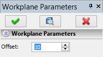
Upon the confirmation by the option ![]() , the workplane being created assumes its new position according to the specified offset.
, the workplane being created assumes its new position according to the specified offset.
There is another way of creating a workplane on a 3D element. While the system is in the command waiting mode, move the pointer to the 3D element (a flat face or edge) and right click ![]() . In the coming up context menu, select the command "Create|Construct Workplane". As a result, the workplane creation command will be launched, with automatic selection of this 3D element.
. In the coming up context menu, select the command "Create|Construct Workplane". As a result, the workplane creation command will be launched, with automatic selection of this 3D element.
Alternatively, when selecting a face, in the same context menu you can select the command "Draw On Face". As a result, a workplane will be created based on the specified face, and the system will enter the mode of working on the active workplane.