Creating Workplane for Auxiliary 2D View |
  
|
Creating Workplane for Auxiliary 2D View |
|
The workplane for an auxiliary 2D view is created using the option:
![]() <D> Construct auxiliary Workplane
<D> Construct auxiliary Workplane
Workplane creation for an auxiliary 2D view is most often used in the technique "From 2D to 3D". As a reminder, let us mention that the 3D model creation is based in this case on a completed 2D drawing. First, workplanes are created according to the views of the drawing. Next, auxiliary 3D elements, such as nodes and profiles, are created based on 2D constructions. The 3D model is finally built based on the created auxiliary elements.
If a 2D drawing contains only main part views, creating just standard workplanes is enough. However, if additional views are present on the drawing (auxiliary or local section views, or simple slanted sections), whose projection plane is not parallel to any of the standard workplanes, you may need to use a workplane based on an auxiliary 2D view. Such a plane is oriented orthogonal to the selected auxiliary view direction. Therefore, creating a workplane based on an auxiliary 2D view amounts to "re-creating" the imaginary underlying plane of the projection defined by this auxiliary view.
Note: the terms "projecting", "section" and "views" used in this chapter refer to general concepts of drafting and design, rather than to the T-FLEX CAD elements "2D Projection", "Section" or the 2D detailing element "Drawing View". The use of those terms is unrelated to the means of design which can be, for instance, manual drafting of a part's 2D representation.
Plane creation procedure
The preconditions to creating an auxiliary view-based workplane are as follows. The 2D drawing of the part must be fit with all necessary main views and sections of the part, including the source auxiliary view. The source workplane must be created in the 2D window. This workplane must correspond with the part view that defines the view direction or the section plane of the auxiliary view in question.
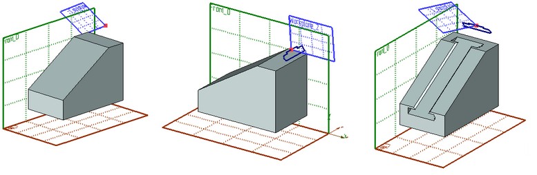
For clarification, let's review the following example. Suppose, a 3D model is built based on the 2D drawing shown below. The general shape of the part was "re-created" by the front view and the top view. Now, we need to create a slot on the slanted face of the part based on an existing view "A".
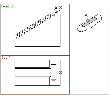
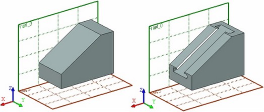
To create the slot, we need to create a workplane orthogonal to the view direction of the local view "A". This plane will help creating a 3D profile based on the view image. The resulting profile will then be used for creating the slot using an extrusion and a Boolean subtraction.
The workplane of the view "A" will be orthogonal to the "Front" plane. Their intersection line must be orthogonal to the arrow marking the view direction.
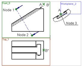
The workplane creation starts with specifying two 2D nodes ("Node 1" and "Node 2") defining the intersection line between the workplane being created and the existing plane. Upon specifying the nodes, the system automatically identifies the original workplane and the view direction for "projecting" on the auxiliary view plane being created. The workplane viewing direction is marked by two arrows that appear next to the selected nodes. This defines the preliminary positioning in the space of the workplane being created.
The choice of the original plane and the view direction can be modified, if necessary. Note also, that the view direction initially defined by the system depends on the order of the nodes selection.
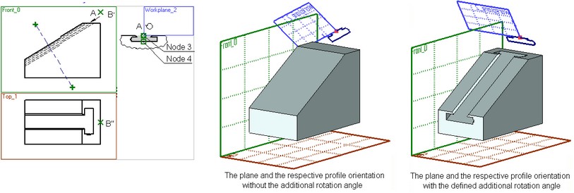
The next step is selection of a 2D node for the attachment point of the workplane being created on the 2D page. Normally, you select one of the 2D nodes belonging to the auxiliary view image. The same node defines the workplane borders and its local coordinate system origin. The first corner of the plane border rectangle will be at the selected node, while the second, the diagonal one – at the nearest corner of the drawing format frame on the current document page. In the example, let's select "Node 3" as the attachment node for the plane being created. The newly created workplane border rectangle is then displayed on the current page of the drawing.
The local coordinate axes of the plane being created are automatically rotated, together with the plane itself, by the angle equal to that between the planes' intersection line and the vertical. This ensures the correct positioning in the space of the 3D elements that will be created on this plane from the lines of the auxiliary view.
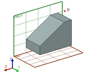
Additionally, one can define a 3D node for the workplane being created to pass through. This step is optional. If no 3D node is specified, then the plane will be constructed through the world coordinates origin. The plane is positioned in the space in such a way, that the 2D attachment node defined at the previous step becomes the projection of this 3D node on the plane being created. The attachment 3D point defines the exact positioning of the plane being created in the space.
In the described example, the new plane positioning is adjusted by using the 3D node "B" (constructed from its projections B' and B''). As a result, the plane will assume the position shown on the following diagram.
To view the new plane position in the 3D space, set the flag in its parameters that controls the plane display in the 3D scene.
When creating a workplane of an auxiliary view, you can redefine the plane borders in the 2D window. To do this, specify 2D nodes on the current page of the document as the corners of the displayed plane border rectangle. This can be skipped in the described example.
Note the hatch shown as gray filling on the view "A". If you create a 3D profile on the new plane based on this hatch, then the profile will be positioned just as a part element supposed to be in order to yield the projection on the created plane per the view "A".
If the image on the view "A" were rotated as shown on the diagram below, then we would need to additionally define the rotation angle for the plane being created. In such a case, two additional 2D nodes are to be specified ("Node 3" and "Node 4") to define the rotation axis. As a result, the local coordinate system of the plane being created is rotated additionally by the angle equal to that between this axis and the intersection line between the planes.
Plane creation
Creation of a workplane based on an auxiliary 2D view is done by using the following option in the command automenu:
![]() <D> Construct auxiliary Workplane
<D> Construct auxiliary Workplane
Upon selecting this mode, the additional options appear in the automenu:
![]() <D> Select 1st/2nd Node of view direction
<D> Select 1st/2nd Node of view direction
![]() <W> Select Other Workplane
<W> Select Other Workplane
![]() <A> Set view rotation
<A> Set view rotation
![]() <Tab> Switch view direction
<Tab> Switch view direction
![]() <N> Set Attachment point
<N> Set Attachment point
![]() <M> Set relation with Node
<M> Set relation with Node
![]() <B> Define Workplane borders
<B> Define Workplane borders
The default option ![]() is activated upon turning on the mode of creating the plane by an auxiliary 2D view. This option allows selecting subsequently two nodes in the 2D window (using
is activated upon turning on the mode of creating the plane by an auxiliary 2D view. This option allows selecting subsequently two nodes in the 2D window (using ![]() ), which define the planes intersection line. Upon selecting the first node, the system automatically determines and highlights the original workplane candidate. If a wrong plane was selected by the system, it can be changed by the option
), which define the planes intersection line. Upon selecting the first node, the system automatically determines and highlights the original workplane candidate. If a wrong plane was selected by the system, it can be changed by the option ![]() . Upon specifying the second node, the view direction of projecting on this plane is determined. The initially determined view direction can be flipped by the option
. Upon specifying the second node, the view direction of projecting on this plane is determined. The initially determined view direction can be flipped by the option ![]() .
.
Upon specifying both 2D nodes and, therefore, the intersection line between the planes, the option ![]() activates automatically in the automenu. It allows selecting the plane attachment node on the drawing page in the 2D window. The plane creation can be finished at this time by pressing
activates automatically in the automenu. It allows selecting the plane attachment node on the drawing page in the 2D window. The plane creation can be finished at this time by pressing ![]() in the command automenu or in the property window. Alternatively, you can continue with the plane creation by selecting a 3D node with the option
in the command automenu or in the property window. Alternatively, you can continue with the plane creation by selecting a 3D node with the option ![]() , for the plane to pass through. This option activates automatically in the automenu after defining the attachment 2D node.
, for the plane to pass through. This option activates automatically in the automenu after defining the attachment 2D node.
The default workplane borders can be modified using the option ![]() . Modifying borders of a workplane by an auxiliary 2D view is similar to modifying the borders of other types of workplanes described above.
. Modifying borders of a workplane by an auxiliary 2D view is similar to modifying the borders of other types of workplanes described above.
Additional rotation of the plane coordinate system (when dealing with a rotated image view) is defined by the option ![]() . Upon activating the option, specify two additional 2D nodes. The rotation direction depends on the order of selecting the nodes.
. Upon activating the option, specify two additional 2D nodes. The rotation direction depends on the order of selecting the nodes.