Creating Workplane through a 3D Point |
  
|
Creating Workplane through a 3D Point |
|
To create a workplane based on a 3D point, you need to select the following option in the command's main automenu:
![]() <3> Select first 3D Point of Workplane position
<3> Select first 3D Point of Workplane position
Using this option, you can select a 3D element in the 3D scene, that defines the necessary point. This could be a 3D node, a body vertex, a center of an elliptical edge or a midpoint of a straight one, an LCS origin, etc. The coordinate origin of the workplane being created will be positioned in the selected point.
The following additional options we will appear in the automenu after picking the option ![]() :
:
![]() <3> Select first 3D Point of Workplane position
<3> Select first 3D Point of Workplane position
![]() <4> Select a line through which the workplane goes
<4> Select a line through which the workplane goes
![]() <5> Select second 3D Point of Workplane position
<5> Select second 3D Point of Workplane position
![]() <7> Select third 3D Point of Workplane position
<7> Select third 3D Point of Workplane position
![]() <8> Select Plane from which Workplane angle is measured
<8> Select Plane from which Workplane angle is measured
![]() <9> Select Direction
<9> Select Direction
![]() <T> Select Surface to which the Workplane is tangent
<T> Select Surface to which the Workplane is tangent
Using these options, you can construct the following types of workplanes based on the selected 3D point:
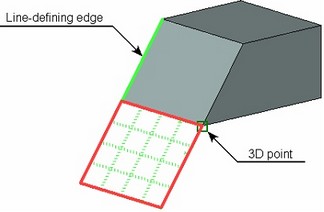
- Workplane going through a 3D point and a line;
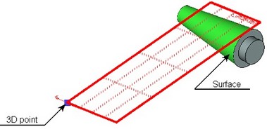
- Workplane going through a 3D point and tangent to a cylindrical or conical surface.
- Workplane going through two 3D points;
- Workplane going through two 3D points and in the specified direction (or through two points at an angle to the specified direction);
- Workplane going through two 3D points at an angle to a plane;
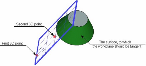
- Workplane going through two 3D points and tangent to a conical, cylindrical or spherical surface.
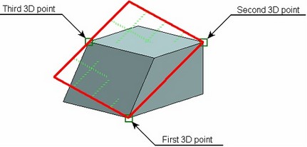
- Workplane going through three 3D points.
To construct Workplane going through a 3D point and a line, after selecting the base 3D point you need to specify a line, through which the plane should go. The line is selected with the option ![]() . The selected line should not go through the coordinate system origin point. In this case, the X-axis of the coordinate system of the workplane being created will be directed along the selected line, while the Y-axis will be going through the coordinate system origin point perpendicular to the line.
. The selected line should not go through the coordinate system origin point. In this case, the X-axis of the coordinate system of the workplane being created will be directed along the selected line, while the Y-axis will be going through the coordinate system origin point perpendicular to the line.
To construct Workplane going through a 3D point and tangent to a conical or cylindrical surface, after defining the 3D point you need to select the desired surface with the option ![]() . From the two tangency possibilities, the one will be selected that is closer to the cursor position at the instant of selecting the surface.
. From the two tangency possibilities, the one will be selected that is closer to the cursor position at the instant of selecting the surface.
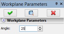
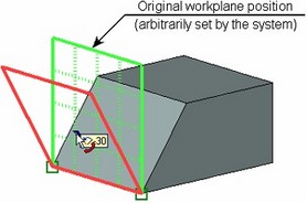
To construct Workplane going through two 3D points, you need to select an additional 3D point after selecting the first 3D point, using the option ![]() . The workplane is constructed as going through the axis defined by the selected 3D points. The workplane position in the space is set arbitrarily by the system. If necessary, the workplane position can be modified by rotating it at the specified angle relative to the original position. The angle is defined in the command's properties window or directly in the 3D window using a dragger.
. The workplane is constructed as going through the axis defined by the selected 3D points. The workplane position in the space is set arbitrarily by the system. If necessary, the workplane position can be modified by rotating it at the specified angle relative to the original position. The angle is defined in the command's properties window or directly in the 3D window using a dragger.
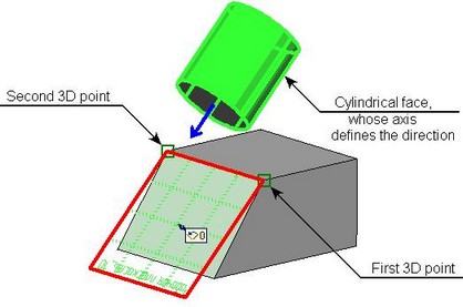
To construct Workplane going through two 3D points in the specified direction, after defining the first 3D point you need to select the second 3D point (the option ![]() ) and a 3D element defining a direction (the option
) and a 3D element defining a direction (the option ![]() ). The direction can be defined with a planar edge or 3D path, a normal to a surface, an axis of a cylindrical or conical surface, etc.
). The direction can be defined with a planar edge or 3D path, a normal to a surface, an axis of a cylindrical or conical surface, etc.
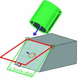
If necessary, it is possible to define an additional rotation angle of the workplane relative to a specified direction (in the properties window or in the 3D window using a dragger).
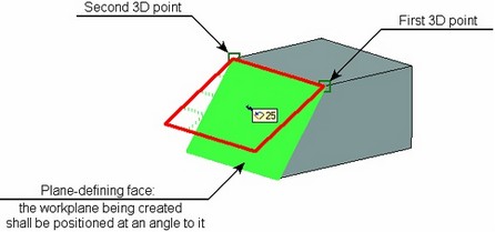
To construct Workplane going through two 3D points at an angle to a plane, after defining the first 3D point you need to select the second 3D point (the option ![]() ) and a plane (the option
) and a plane (the option ![]() ). To define a plane, you can select another workplane, a flat (planar) face, a planar edge, an LCS, etc. As in the previous cases, the angle is defined in the properties window or in the 3D window using a dragger.
). To define a plane, you can select another workplane, a flat (planar) face, a planar edge, an LCS, etc. As in the previous cases, the angle is defined in the properties window or in the 3D window using a dragger.
To construct Workplane going through two 3D points tangent to a surface (conical, cylindrical or spherical), you need to specify the first 3D point, and then the second 3D point (the option ![]() ) and a surface (the option
) and a surface (the option ![]() ). The X-axis of the created workplane coordinate system will be directed from the first selected point to the second one.
). The X-axis of the created workplane coordinate system will be directed from the first selected point to the second one.
When selecting a conical or cylindrical tangency surface, the construction result will be defined similarly to that of a workplane by a single 3D point with a tangency to a surface. The second point definition could merely help define the tangency configuration.
To construct Workplane going through three 3D points, you need to define the first 3D point, then select the second 3D point (the option ![]() ) and the third 3D point (the option
) and the third 3D point (the option ![]() ). The X-axis of the created workplane coordinate system will be directed from the first selected point to the second one, and the Y-axis will be perpendicular to it.
). The X-axis of the created workplane coordinate system will be directed from the first selected point to the second one, and the Y-axis will be perpendicular to it.
The workplane creation must be confirmed by the option ![]() .
.