Сreating Workplane Based on LCS |
  
|
Сreating Workplane Based on LCS |
|
A local coordinate system (LCS) is an auxiliary 3D construction element used for defining 3D object positions in the space. A workplane based on an LCS coincides with one of its principal planes – XY, XZ, YZ. Since LCS axes can be directed arbitrarily, use of this construction technique allows positioning the workplane in any desired point in the space and in any orientation.
To create such workplane, in the main command automenu select the option:
![]() <L> Construct Workplane based on LCS
<L> Construct Workplane based on LCS
As a result, the following actions are accessible:
![]() <N> Set Attachment point
<N> Set Attachment point
![]() <L> Select target LCS
<L> Select target LCS
![]() <B> Define Workplane borders
<B> Define Workplane borders
To create the workplane, just select a local coordinate system (in the 3D window or in the 3D model tree) using the option ![]() . The image of the workplane being created will be instantly displayed in the 3D window, coinciding (by default) with the XY plane of the selected LCS. One of the corners of the displayed workplane border rectangle will be at the LCS origin. At this step, you can already complete the plane creation by pressing
. The image of the workplane being created will be instantly displayed in the 3D window, coinciding (by default) with the XY plane of the selected LCS. One of the corners of the displayed workplane border rectangle will be at the LCS origin. At this step, you can already complete the plane creation by pressing ![]() . In this case, a separate "Workplane"-type page will be created in the 2D drawing for the new workplane.
. In this case, a separate "Workplane"-type page will be created in the 2D drawing for the new workplane.
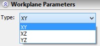
You can change the default positioning of the plane with respect to the source LCS. Firstly, you can set a different principal plane of this coordinate system. To do this, in the property window select the desired option. As you do, the workplane image in the 3D window will instantly adjust its position.
Secondly, you can select a 2D node in the 2D window, using the option ![]() , to be assigned as the origin of the coordinate system. In this case, the workplane is created on the page of the 2D drawing to which the selected 2D node belongs. The image of the plane in the 3D window will move to make the LCS coincide with the point on the plane defined by this node.
, to be assigned as the origin of the coordinate system. In this case, the workplane is created on the page of the 2D drawing to which the selected 2D node belongs. The image of the plane in the 3D window will move to make the LCS coincide with the point on the plane defined by this node.
Finally, you can additionally change the size and position of the displayed borders of the workplane, using the option ![]() . The borders are changed in the same way as when creating a standard plane.
. The borders are changed in the same way as when creating a standard plane.