Bending |
  
|
Bending |
|
General Information
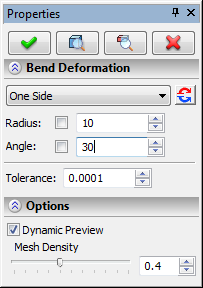
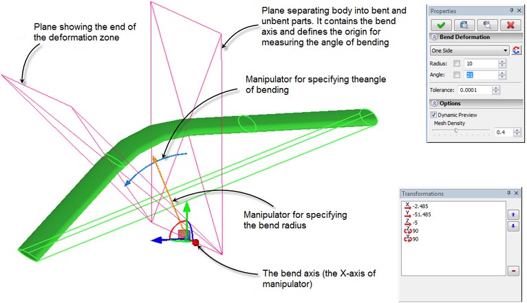
Bend deformation allows us to bend a selected body with respect to the selected axis by a specified angle. To create this deformation, a user has to specify the deformed body, the origin and the direction of the bend axis, the angle and the bend radius.
To specify the bend axis, the angle and the bend radius, it is possible to use the special multi-element manipulator in the form of LCS with additional elements for specifying the angle and the bend radius.
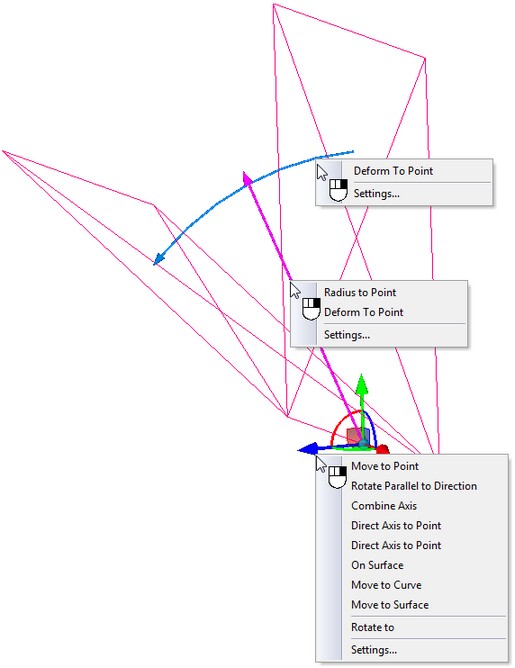
For all elements of the manipulator of the operation, are available the context menus with the set of additional options that simplify positioning of the manipulator and specification of the parameters of bending.
The angle and radius of bending can be specified both with the help of the manipulator and as the numeric values in the dialog of the command's properties window.
The bend radius defines the position of the “neutral” surface. For the source body, this is the plane that turns into the cylinder on the bent body. The points lying on this surface do not undergo the tension or compression deformation.
In this operation, it is possible to quickly change the part of the body being deformed, and also, create two-sided bending (with respect to the dividing plane).
As in the sculpt deformation, in the bend deformation it is also possible to modify the size of the deformation area (the size of the deformation area bounding parallelepiped). By default, it spans the entire body.
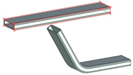
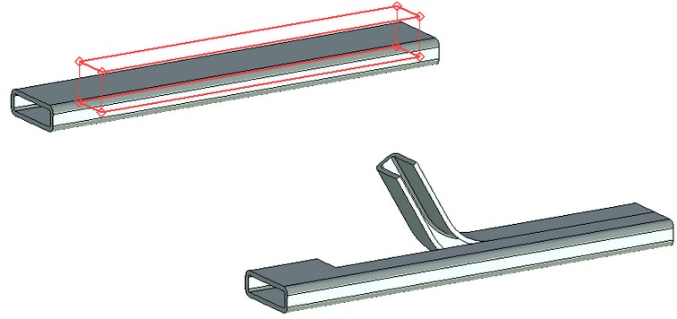
The deformation area spans the entire body The deformation area spans only a part of the body
Creating Bend Deformation
For creating the bend deformation, use the command “3DRB: Bend Deformation”:
Icon |
Ribbon |
|---|---|
|
3D Model → Special → Deformation → Bend Deformation |
Keyboard |
Textual Menu |
<3DRB> |
Operation > Deformation > Bend Deformation |
After invoking this command, follow these steps:
1.Select deformed body;
2.Define the origin of the bend axis;
3.Define the direction of the bend axis;
4.Define the normal to the plane dividing the deformed and undeformed parts of the body;
5.Select deformation area (if necessary);
6.Specify the bend radius and the bend angle;
7.Select the mode of creating deformation (deformation of the selected part of the body, deformation of the opposite part or two-sided deformation);
8.Complete the operation creation by pressing ![]() .
.
Selection of Deformed Body
To select the deformed body, the following option of the automenu is used:
|
<O> |
Select Body to Deform |
This option is turned on by default upon the entry into the command. The deformed body is selected with the help of ![]() in the 3D window or in the tree of the 3D model. The selected body is highlighted.
in the 3D window or in the tree of the 3D model. The selected body is highlighted.
Selection of Bend Axis and Body-Dividing Plane
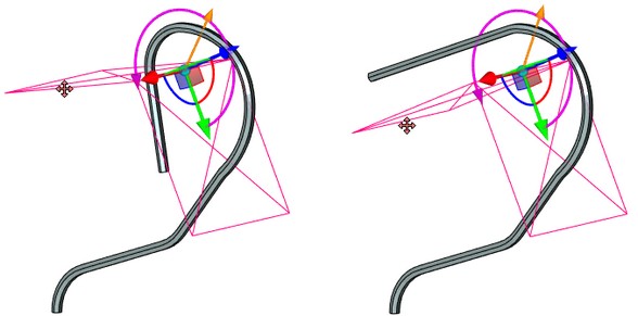
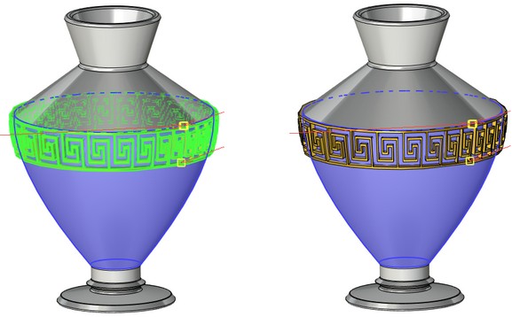
After selection of the deformed body, the manipulator for specifying parameters of bending appears in 3D scene. By default, the axes of the manipulator are oriented along the sides of the bounding parallelepiped of the bent body. The axis of bending coincides with the X-axis of the manipulator. The plane that separates the bent and unbent parts of the body is defined as the X-Y-plane of the manipulator.
The work with the manipulator of the bending deformation is similar to that of analogous manipulators in other commands of T-FLEX CAD.
Specifying Bend Angle and Radius
A user can specify the numeric parameters of bending deformation – bend angle and bend radius – in different ways. The exact values of these parameters can be specified in the dialog of the command's parameters (parameters “Radius”, “Angle”). Or they can be defined by using the draggers in the 3D window. To specify the values of the angle and radius with the help of the draggers, bring the cursor to the corresponding dragger, press In the context menu of the manipulators for specifying the angle and the radius, are also accessible the commands for specifying the values of the radius and the angle with the help of 3D points. |
|
With the help of the button ![]() in the dialog of the command's properties, a user can quickly change the direction in which the bend angle is measured.
in the dialog of the command's properties, a user can quickly change the direction in which the bend angle is measured.
Selection of Bending Mode. Modifying Size of Bending Area
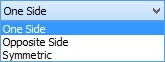
The mode of creating deformation is specified in the command's properties window with the help of the drop down list “Mode”. By default, the value “One Side” is set, which means that the deformation will be applied only to one part of the initial body (the part which is chosen by the system by default). If a user wants to apply the deformation to another part of the body, he should turn on the option “Opposite Side”. |
|
For creating two-sided deformation, that is bending of both parts of the body, the option “Symmetric” should be used.
The bounding parallelepiped of the deformation area initially spans the entire body. For modifying the size of the deformation area, as in the sculpt deformation, the following option of the automenu is used:
|
<D> |
Change Deformation Box |
Modifying the deformation area is carried out similarly to the sculpt deformation (see above). To exit the mode of modifying the size of the deformation area, in the automenu turn off the option ![]() .
.
Options in Deformation Operations
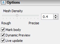
In the process of specifying/editing parameters of deformation, the future result of the current operation is dynamically shown in the 3D window. For speeding up the work, the dynamic preview can be turned off by taking off the flag “Dynamic Preview” in the command's properties window.
An additional parameter “Mesh Density” controls accuracy of the mesh used for visualization of the result of the deformation. The increase in the mesh density leads to slower regeneration of the bodies in the scene but increases accuracy of the drawing. |
|
If you disable option Mark body, the body is no longer highlighted in the scene, which simplifies visual perception of the deformed object.
On |
Off |
The Live update option allows to watch deformations of the body in real time. Deactivating the option accelerates recalculation because solid body updating is not required.