T-FLEX CAD supports construction lines defined by explicit mathematical formulation. Such construction lines are called functions. To define a function, specify its definition type (parametric, plain, etc.), the start and end of the parameter range, various display parameters of the curve.
You can work in two modes: either using a predefined formula from the provided set, or creating a new function. The set of predefined functions is stored in the file "function.dat". The file name is defined in the item "Function spline file" of the command "SO: Set System Options" ("Customize|Options|Files"). The file "function.dat" can be edited or replaced, if desired. Notations for the parameters, accepted in the file, are as follows: #1 – first parameter, #2 - second parameter of the function (can be optional). Follows is a detailed description of these parameters.
The system treats the resulting construction line of the function as a spline, therefore, the <S> key is used for its selection in various commands.
Defining the function
The entities defined by a function are input via the command "FU: Construct Function Spline"
Icon |
Ribbon |
|---|---|
|
Draw → Construct → Function Spline |
Keyboard |
Textual Menu |
<FU> |
Construct > Function Spline |
The following options are available to the user:
|
<Enter> |
Select nearest node or create node defining the function coordinate system |
|
<Ctrl><F> |
Free mode on/off toggle |
|
<N> |
Select Node |
|
<P> |
Set entity Parameters |
|
<A> |
Select axis of symmetry axis (straight line) |
|
<F4> |
Execute Edit Construction command |
|
<Esc> |
Exit command |
The function spline construction entity allows defining construction entities of virtually any kind. The main condition is possibility of defining construction entities in a form of functional relation between the coordinates.
The system provides an option of selecting predefined functions defining various curves, such as parabola, evolventa, spiral, etc. You can also define your functions independently, and then use them. For this purpose, create a descriptor file or append an already existing one with new formulas and values of other parameters defined in the function parameters dialog box.
The definition procedure includes two stages:
1. Defining the coordinate system position (X and Y). The coordinate system helps defining the desired position of the resulting entity on the drawing. The coordinate system is defined by sequential selection of two nodes. The first node defines the origin (0,0). The second node defines the direction of the X-axis. The Y-axis is defined automatically based on the origin and the X-axis positions.
2. Defining the functional relation and other parameters. This is done in the function parameters dialog box that appears on the screen after selecting the second node.
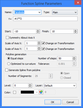
The following parameters are defined in the function parameters dialog box:
Name of the formula. One can select from the list a name of a standard function or define an arbitrary name for creating a new function.
Type, or the way of defining the function. Four different types of definition can be used:
- Plain definition in Cartesian coordinates (Y = f (X)) Example: Y= #1**2 defines a parabola. The notation #1 is used for the variable parameter (in this case - X). This special notation is used to avoid confusion with the system variable names that can be used in the expression defining the functional relation. Besides variables, functions can be used as well as they are supported for use in the variable editor.
- Parametric definition in the Cartesian coordinate (X = f(t), Y = f (t)). Example: X = #1, Y = #1 defines a straight line.
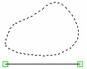
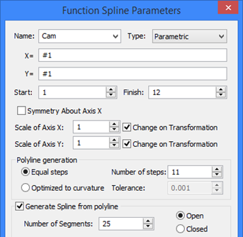
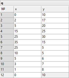
One can create, for instance, a database of cam coordinates, and then use a parametric definition for the cam contour. Use the database access functionality and define a parametric relation where the variable parameter #1 is the record number in this database. The specified number of steps must necessarily equate with the difference between the end and start values of the function variable parameter.
The indicator of the end value, or the end record, in the database named "q" can be conveniently entered as the expression "q.#", returning the number of the last record in the database q.
- Function in Polar coordinates (P = f (A))
Example: P = #2 defines a circle with the radius equal to the value of the parameter #2. #2 – is the second special notation that can be used in function defining expressions. It is equal to the distance between the nodes that define the coordinate system.
-Parametric definition in Polar coordinates (A = f(t), P = f(t)).
In T-FLEX system, such definition of functional relations may be convenient in a number of situations. For example, suppose, a database stores the values of angles and distances of a cam coordinates. Use the database access functionality and define a parametric relation where the variable parameter #1 is the record number in this database.
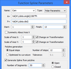
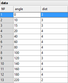
X=, Y= (or A=, P=) Depending on the type of the function being defined, these two fields describe the expressions defining Х and Y (for functions in Cartesian coordinates) or A, P (for functions in Polar coordinates). The following notations are used: #1 – the first parameter, #2 – the second parameter of the function (can be optional).
The resulting function construction, as in the case of splines, is a polyline. The "Start" and "Finish" parameters define respectively the start and end values of the variable parameter, defining the beginning and the end ranges of calculating the polyline coordinates.
The "Polyline generation" group of parameters defines the way of calculating the intermediate point coordinates when creating the polyline:
Equal steps. This way implies the variable parameter to change from the start to the end value in equal increments. The number of steps is specified by the user. It defines the number of segments in the polyline being created. The more the number of steps, the higher-accuracy will be the polyline representation along the bends and the longer time will take various operations handling the created polyline.
The number of points used in the polyline creation is always equal to the number of segments plus one, and, therefore, is greater by one than the specified number of steps. The first point always corresponds to the start value of the variable parameter. The coordinates of the rest of points are based on the values of the variable parameter defined by the formula:
Current value = Start value + I * Step
Step = (End value – Start value) / Number of steps,
I is the current step number (1,2,…, Number of steps).
If polyline point coordinates are calculated using a database, the value of the variable parameter is usually the line number in the database. In this case, the current value of the variable parameter is replaced by the largest integer less than or equal to it. As a result, data could come at uneven steps from the database. To avoid this, always define the function parameters in such a way that the number of steps was equal to the difference between the end and the start values of the variable parameter.
Optimized to curvature. One could notice that the above approach is not always convenient for curves of complex shape, as the tessellation density was constant along "smooth" and "curved" zones unnecessarily. Optimization to curvature yields finer tessellation along high-curvature zones and, respectively, coarser otherwise. The criterion of the accuracy and quality in this case is the "Tolerance" parameter that defines the maximum permitted deviation of the calculated polyline coordinates from the true curve coordinates. The lesser is the tolerance, the more segments will be in complicated zones of the curve.
Once the polyline is built, it can directly be used as a construction entity. However, a possibility is provided for using the calculated polyline points for spline creation. For this, turn on the option "Generate spline from polyline", define its type and the number of tessellation segments between two neighboring points of the spline for the spline tessellation polyline. This tessellation polyline will be the final output construction entity. Spline generation may be needed when a smooth curve is desired, while the number of defining points is limited.
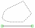
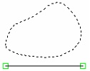

The "Symmetry About Axis X" flag among the function spline parameters allows mirroring of the created entity about the X-axis of the function local coordinates. (The X-axis passes through the two nodes selected at function spline creation).
If in future this construction line will be subjected to a symmetry transform (for instance, in copying or in translation), then the state of the flag of the transformed line may be changed by the system automatically.
To construct a spline symmetrical to a given one about an arbitrary line, use the option ![]() .
.
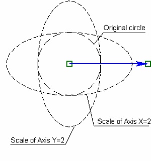
Additional parameters "Scale of Axis X (Y)" allow changing the scale along each axis of the function local coordinate system. The coordinate of each point used in the function creation is multiplied be the specified scale factor. The "Change on Transformation" flags, to the right of the respective axis scale input boxes, allow/disallow automatic change of scale when subjecting the given entity to a scaling transform (as in copying or translation). The cleared flag prohibits automatic change of the respective scale factor, while the checked item allows it.
Note that special-type nodes are created at end points of function spline construction entities (as well as in other curves). These are created by using the option ![]() of the node creation command.
of the node creation command.
Evolventa creation example
As an example, let's create a profile of a cogwheel. First, let's make all necessary calculations and constructions: circles, cog size, etc. relating these parameters by variables.
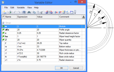
Then, using the "Evolventa" function, specify two points for defining the Õ-axis of the evolventa. Besides, the first point also defines the center of the main circle (rb). Each equation among the function parameters needs to be multiplied by the main radius of the wheel or by the #2 parameter, the latter being the case when defining the main circle radius by the second point.
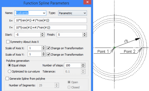
Besides, the start and end points (angles) can be defined among the evolventa parameters. This is optional, since the evolventa will be bounded by the specified radii of the wheel being created.
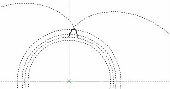
In the reviewed example (see the diagram) a general case of evolventa is limited to sampling an upper portion of a cog profile. This drawing is located in the folder "Examples/ 2D Design/ Function Splines / Evolventa.grb". Do not use this file as a template for designing cogwheels. Follow the design insights of this document and use refined formulas to create a complete profile of a cog. Use this drawing in future for creating other cogwheels.
Editing function spline
Editing of the function spline construction entities is supported by the command "EC: Edit Construction".
Icon |
Ribbon |
|---|---|
|
Draw → Additional → 2D Construction |
Keyboard |
Textual Menu |
<EC> |
Edit > 2D Construction |
After entering the command, you can reassign the defining nodes of the coordinate system or modify parameters. As for splines, use the option <S> for selecting function spline construction entities.