Route |
  
|
Route |
|
The route is a special type of a 3D path, that is composed of straight segments. The adjacent straight segments are connected by arcs of a specified radius. This type of a 3D path is mostly intended for defining a spatial trajectory used for creating routes.
Types of route segments
For each segment of a route you can specify the type that determines the way of its construction:
- Spline by polygonal line. Spline of arbitrary degree based on control polygonal line. Control points are used for construction of control polygonal line. The spline itself does not pass through these points (except the first and the last points). The degree can be specified in parameters of the spline.
●Spline degree is a degree of polynomials of a piece-continuous function that describes the spline being created. The maximum admissible value of the degree must be smaller by one than the number of spline points. For a spline containing no fewer than four control points the degree of 3 is selected by default. The higher degree of a spline, the more "rigid" it becomes. This means that it weakly reacts to the translation of an individual control point. Splines of lower degrees pass closer to the control points and the change in their location affects the shape of a spline more significantly.
- Spline by points. Spline passing through all given points. When creating a 3D spline through the nodes, it is possible to additionally specify spline direction vectors at the boundary points of a segment (start and end points); a tangent line at other points of a spline.
- Polyline. It constitutes a spatial polygonal line composed of segments of the lines that join the points of the initial set. Polyline can be both open and closed (when creating a closed polyline the first 3D point of the initial set is used twice – for determination of the beginning and the end of the path).
Connecting route segments
If it is necessary to combine in one 3D path the segments of different types the system automatically constructs a transition from one segment to the next one. The initial point of a segment might not coincide with the end point of the previous segment. In this case, between the segments the transition zone is constructed in the form of a curve joining these segments. If possible, the system will construct a smooth fillet. The «Tangency at the start», «Tangency at the end» parameters allow us to specify the radius of curvature at the tangency points. Values of these parameters can be modified with the help of manipulator in 3D window or with the help of the numeric value in the properties window.
Using manipulators
When adding a new point of the 3D path the LCS manipulator appears in the scene that allows us to change location of the point with respect to the selected attachment (absolute coordinates, 3D node, vertex, etc.). By default directions of the manipulator axes coincide with the directions of the global coordinate system axes.
Manipulator provides for the following transformations:
- translation along the axis (X, Y, Z). To enable translation, move the cursor closer to the axis arrow.
- translation in the plane (XY, XZ, YZ). To enable translation, move the cursor closer to the image of the plane.
- translation by three axes. To enable translation, move the cursor closer to the sphere at the center of the manipulator.
- rotation about the axis (X, Y, Z). To enable rotation move cursor closer to the arc (the color of the arc corresponds to the color of the axis around which the rotation will be carried out).
Manipulator can work in one of the two modes:
- numeric specification of the transformation value. To work in this mode move the cursor of the mouse closer to the manipulator (it will be highlighted and the tip will appear on the screen) and translate the mouse with the pressed left button. Precise value of the transformation can be specified on the system toolbar.
- transformation is prescribed by snapping to the existing object of the model (for example, translation up to a 3D node). To work in this mode move the cursor of the mouse closer to the manipulator and click ![]() . After that the object snapping will be working upon translation of the cursor. In this way it is possible to specify the translation up to a point, edge midpoint, etc.
. After that the object snapping will be working upon translation of the cursor. In this way it is possible to specify the translation up to a point, edge midpoint, etc.
Any change in the location of the manipulator is reflected in the auxiliary window «Transformations». For each point of the path a separate list of transformations is saved. Translations along the axes are summed up. Transformations with the use of object snapping are recorded as a separate line. Transformation selected in the list can be deleted. The object snapping can be redefined by indicating a new object in 3D scene.
The order of transformations can be changed by moving transformation up and down along the list with the help of buttons with arrows. However, it is important to take into account the fact that an arbitrary change of the order might lead to the incorrect result.
Snapping manipulator to the elements of the model. Using context menu in work with the manipulator
When selecting one of the manipulators mentioned above the following commands will become available in the context menu:
- for translation along the axis
- for translation in the plane
- for translation along three axes
- for rotation around the axis
The option of the «Settings» menu defines the step with which the distance and the angle change upon translations and rotations of the manipulator.
Manipulator of rounding
Manipulator that controls rounding of the path is available at any point of the segment, except the start and the end points. Translation of the manipulator changes the value of rounding in the selected point. For input of the numeric value the «Rounding» field in the properties window is used. By default all points of the segment have the same value of rounding – the «Radius of rounding» field.
For the manipulator of rounding there is a limitation – minimum radius, i.e., the manipulator with the radius as small as desired cannot be specified. For input of small values of rounding, the field in the properties window must be used.
Tangency manipulator (available only for a spline by points)
- tangent to a curve at a point. The length of the tangent vector is specified.
- direction of tangent. Two manipulators in the form of arcs that allow us to specify direction of the tangent. For these manipulators the two commands: «Tangent along the direction up to a point» and «Tangent along the direction» are available in the context menu.
Tangent in the direction up to a point allows us to select a point that defines the direction of the tangency vector. Tangent along the direction allows us to select an object that defines the direction of the tangency vector. Direction can be specified by an edge, normal to a surface, axis of the coordinate system, etc.
Manipulator for a segment along the path\edge
If a part of the segment is specified as an edge or 3D path, the following manipulators will be displayed in the scene:
- location. Specifies the offset from the ends of the selected object. The precise value can be specified on the system toolbar. In the context menu of the manipulator the «Position in the nearest point» and «Delete a point» commands are available that allow us to specify\cancel the snap of the offset to a point.
- offset (available only for straight segments of the path). Specifies the offset of the segment of the path from the selected object. The precise value is specified on the system toolbar.
- starting angle (available only for straight segments of the path). Specifies the angle of rotation around the selected edge/path. Precise value of the angle is specified on the system toolbar.
- twist angle (available only for straight segments of the path). Specifies the angle of rotation of the end point with respect to the start point of the segment. The selected edge/path is considered as the axis of rotation.
Segment by Points
The segment by points is created when calling the command by default. In the scene the manipulator is displayed which must be translated to the start point of the path. To determine location of the point the attachment to geometric objects (vertices, edges, etc.) or specification of absolute coordinates/shifts can be used. By indicating sequentially the set of points the path’s segment of various shapes can be created:
polyline |
spline by polygonal line |
spline by points |
Rounding of the path can be specified via the common value «Rounding» or individually for each point of the segment. The options for addition or removal of points of the segment are available in the automenu and properties window. There is a capability of dividing the segment into two parts at indicated point.
Segment by surface
To create a segment by surface it is required to indicate the object of one of the types:
The start point of the segment is created on the surface at the place of the mouse click. By adding the next point, its location can be changed with the help of manipulator. The red arrow (U axis) allows us to translate the point across the selected surface. The value of the translation is specified on the system toolbar.
If necessary, the point of a segment on the surface can be snapped to the node that belongs to the selected face. To do so, select the red arrow of the manipulator, and from the context menu invoke the «Move up to a point» command and indicate the point on the surface.
Green arrow of the manipulator (V axis) moves the point across the surface along the second coordinate V. The values of U, V coordinates at each point of the segment are displayed in the corresponding fields in the properties window.
Blue arrow (Z axis) moves the segment being created along the normal to the surface. The precise value of the translation is indicated in the properties window in the «Shift» parameter. When changing the shift the segment equidistant to the one lying on the surface is constructed.
By changing the values of the parameters mentioned above it is possible to obtain both the simple segment of the path and the segment consisting of several windings around the selected face.
Segment by path or edge
To create a segment by path or edge it is required to indicate the object of one of the types:
After selection of the object, the created segment of the path will entirely coincide with it. With the help of manipulators described above location of the segment and its start and end points can be modified. When creating the path by the set of edges (paths) it is required to add a separate segment for each of them.
Diagnostics of wrong constructions
For intuitive diagnostics of errors that arise during construction of the path, the following parameters can be enabled in the properties window:
●«Show bends»
●«Show radius of curvature less than».
In addition, the system automatically shows diagnostics about the self-intersection of the path, about partial coincidence of segments of the path right after the input of the new point or the segment.
Creating of route
To create the route path there is a separate command:
Icon |
Ribbon |
|---|---|
|
3D Model → Construct → Route |
Keyboard |
Textual Menu |
<3PP> |
Construction >Route |
The same command is invoked from the route creation command with the help of the option of the automenu:
|
<B> |
Create/edit path |
Input of new points
By default the following option is enabled in the command’s automenu:
|
<H> |
Mode of adding points after the active one |
After invoking this command the first segment with the start point is automatically created in the route. This point becomes active. Manipulator is located at the zero point of the global coordinate system.
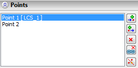
In general, a point is considered active when it is highlighted in the list of points in the properties window. The active point can be changed by selecting another point in the 3D view window or in the list of the properties window.
Several possible actions are available:
Action |
Result |
Pressing the key «Enter» or the option |
Editing of the active point is finished and the new point is created after the active point. The new point is initially located in the same coordinates as the point created just now. The new point becomes active. |
Translation of the manipulator |
Location of the active point is being changed. To confirm the current location of the active point and creation of the new point press the «Enter» key or select the new 3D point. |
Selection of 3D point of the model (3D node, vertex etc.) |
Location of the active point is confirmed, the new point with the snap to the selected object is created. |
Pressing the «Esc» key |
Cancel the last action (translation, snapping, creation of new point). |
Pressing the «Del» key or the |
Delete active point |
Completion of path creation (option |
A route is created. If location of the active point coincides with the previous point, it will not be included into the path. |
If it is required to add new points before the active one it is possible to switch the mode with the help of the option
|
<J> |
Mode of adding the points before the active one |
In this case the actions and the results will be the same as described above. The only difference is that the new point is added not after but before the active one. If the first point of the path is active, the new points are added to the beginning of the segment.
In the properties window next to the list of points there are the buttons which also allow us to add the points before or after the active point, remove the active point. Pressing the ![]() or
or ![]() buttons confirms location of the active point and creates the new point.
buttons confirms location of the active point and creates the new point.
Editing of points
If it is required to change location of already existing point, the ![]()
![]() options must be disabled. To edit location of the point, select it in the list of points. The point becomes active. Manipulator will be translated to the active point.
options must be disabled. To edit location of the point, select it in the list of points. The point becomes active. Manipulator will be translated to the active point.
Several possible actions are available:
Action |
Result |
Translation of manipulator |
Location of active point is being changed. |
Selection of geometric snapping (3D node, vertex, etc.) |
Location of active point is defined by snapping to the selected object. |
Selection of another point of the segment |
Editing of the point is finished, another point becomes the active one. |
Pressing the «Esc» key |
Cancel the last action (translation, snapping). |
Pressing the «Del» key or the |
Delete active point |
Pressing the «L» key or the |
Deletion of snap of the point to the geometric object. After cancelation, location of the point is stored in absolute coordinates |
Completion of path creation (option |
Changes in the route are saved. |
There is a capability of multiple editing of points. Multiple selection is carried out in the properties window, in the «Points» list. After that, translation of the manipulator will affect location of all the selected points.
Specifying coordinates and offsets of a point
The absolute coordinates of the active point are shown in the properties window. For points of the segment by surface in addition to the X, Y, Z fields the U, V, W coordinates are filled in. For points of the segment by edge the U, V, R coordinates are filled in. The values of coordinates can be changed manually.
When creating or editing a point it is often more convenient to specify the values of the offsets but not their absolute coordinates. For input of this data the group of parameters «Offset» is used. When creating the new point its location initially coincides with the point created just now. By specifying the value of the offset, we translate the active point with respect to the previous one. If the offset are specified upon the editing of the point, then the result will be its translation relative to its current location.
Section points can be specified in the coordinates of an arbitrary LCS. To select\cancel LCS in automenu use options:
|
<C> |
Select LCS |
|
<V> |
Cansel LCS selection |
After selecting a coordinate system, it will be used for the current point and all points that are created after the current one. LCS deselection transfers the coordinates of the current point to the global coordinate system. Section of the path can contain any combination of coordinates definition.
Moreover, for each point the value of the radius of rounding (for polyline) and the tangency vector length (for a spline by points) are stored.
By default the following option is active in the automenu:
|
<F> |
Select a point |
That allows us to carry out the snap of the points of the path to geometric objects.
As a point, an object of one of the following types can be selected:
Creation of segments
By default the system creates segments by points. If it is required to construct a path by using geometry of already existing bodies one of the following options is used.
For creation of the segment of the path by path/edge the following option is used:
|
<P> |
Construct segment by path/edge |
After selection of this option the user can select the edge of already existing body or 3D path which will define the trajectory of the segment being created.
Direction of the segment of the path of this type can be changed to reverse with the help of the «Reverse direction» flag. It is convenient to use this parameter when adding new segments in order to provide for the same direction of the path on all segments of the route.
![]()
To create a segment by surface the following option is used:
|
<S> |
Construct segment by surface/face |
After adding the segment, it is required to indicate an object of one of the following types:

The start point of the segment is created at the place of the mouse click. After that, having added the new point, it can be translated with the help of the manipulator or by specifying coordinates U, V in the properties window.
In the properties window the «Pipe diameter» parameter can be specified. If the value is specified, then in the process of specification of segments and points of the path in 3D scene the preview of the route is dynamically displayed. If the value is not specified, then just a 3D path is displayed.
![]()
Adding new segment of route
The list of route segments is displayed in the properties window. To create a new segment the «Add to the end», «Add to the beginning» buttons can be used. To remove the current segment – the «Delete» button. When deleting the segment from the middle of the list the preceding and the following segments are connected via a transitional zone. In the field, located below the list, the type of the curve is displayed (for a segment by points) or geometric object that is a parent (for segments by edge or surface). The type of the segment by points can be modified with the help of the drop down list.
Combining segments of route
Selected segment of the route can be combined with the next segment with the help of the ![]() button located next to the list of segments. If the next segment has a different type, then the combined segment inherits the type of the first segment.
button located next to the list of segments. If the next segment has a different type, then the combined segment inherits the type of the first segment.
In the properties window for a path the «Pipe diameter» parameter can be specified. If the value is specified, then in the process of specification of segments and points of the path in 3D scene the preview of the route creation operation is dynamically displayed. If the value is not specified, then just a 3D path is displayed.
![]()
Existing 3D path can be combined with the other path with the help of the option:
|
<V> |
Merge two paths |
The option is available only when editing an existing path. After calling the option, you must specify the second path. The neighboring points of selected paths will be joint on merging. If the paths are parallel to the joint points are determined randomly.
Existing 3D path can be divided into two paths with the help of the option:
|
<D> |
Split path |
Additional Options
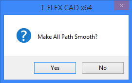
Create smooth path. Smooth transition zones will be added when creating new sections of a path.
When this flag is used for the path that contains multiple sections, you are prompted to smooth transition zones. To do this, select "Yes" in the following message box:
Mark point with curvature less than. When using this option together with the definition of minimum curvature radius, system will indicate points at which this parameter is less than the specified value.
Mark breaks. With this option, the system will mark points at which there is a break in the path, i.e. violated conditions of smoothness (tangent to the right is not equal to the tangent to the left) .
Check self-intersections. This option controls the dynamic definition of intersection points of the path sections. The points of intersection are marked with “Partial overlapping path”." Such points will prevent path creation. Using this option increases system response time, so it is recommended to add verification of the intersection just before the completion of the path creation.
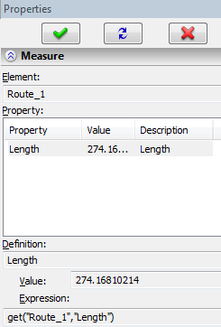
Length of Route Path
To get the value of the route length, use the command "Measure". Measurement command can be called from the context menu of Pipeline operation.
Length is contained in Length parameter.
To call the dialog box of path parameters use option:
|
<P> |
Set entity parameters |
The dialog box of route parameters contains two tabs - "General" and "Transformations". The contents of these tabs is described in detail in the section "General Parameters of 3D Elements".