Main Concepts and Capabilities
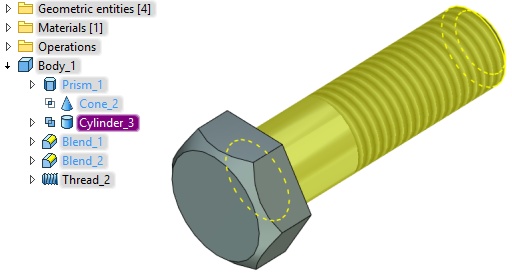
Commands united in the Primitives group allow to create basic geometric bodies: Box, Cylinder, Cone, Sphere, Torus, Prism and Pyramid without additional construction elements creation.
You can specify location and general dimensions for primitives and apply Boolean operation for them immediately. This allows you to quickly create models based on primitives.
Creating Operation
A drop-down list of commands for primitives’ creation can be found in the Primitives group:
Icon |
Ribbon |
|---|---|
|
3D Model → Special → Primitives |
Keyboard |
Textual Menu |
|
Operation > Primitives |
There is also an additional Ribbon tab for primitives:
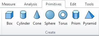
When you select a command from the list the corresponding body appears in the 3D scene.

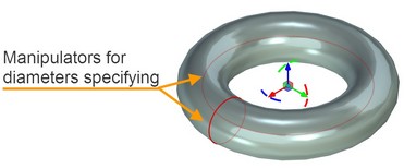
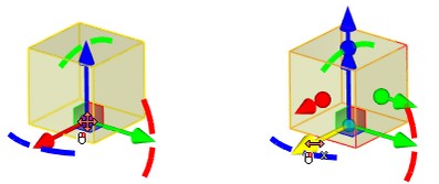
Translation and rotation manipulators and manipulators for geometric parameters specifying are available for the bodies.
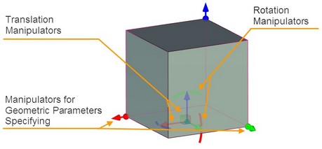
All transformations that are perfored using translation and rotation manipulators are displayed in the properties window in the Transformations section.
Special manipulators are used to change diameters of rotation bodies.
Operation Options
Commands for LCS creation and transformation are available in the automenu of each primitive type.
Source LCA is associated with the primitive and allows you to set its position in the scene. Source LCS can be merged with target LCS, which already exists in the scene. Their axes will be combined.
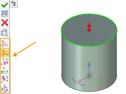
More information about LCS transformation and manipulators for translation and rotation can be found in “Translations” chapter.
Symmetry ![]() option exists in automenu for all commands from Primitive group, except Pyramid command. A single body that consists of two symmetric parts is created after its activation. Additional symmetry operations are not performed in this case. Source coordinate system of the primitive is moved to the center of the body. The option is active for Sphere and Torus by default.
option exists in automenu for all commands from Primitive group, except Pyramid command. A single body that consists of two symmetric parts is created after its activation. Additional symmetry operations are not performed in this case. Source coordinate system of the primitive is moved to the center of the body. The option is active for Sphere and Torus by default.

A ![]() Sheet body option is available for all commands from Primitive group. Bases of the bodies are removed and side faces are left.
Sheet body option is available for all commands from Primitive group. Bases of the bodies are removed and side faces are left.

Possibility to create thin wall element is available for Box, Sphere, Cylinder and Torus.

Thin wall element parameters can be set in Thin Wall section of Properties window.
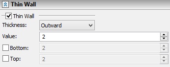
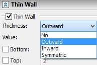
Bottom and top of thin wall element can be set for Box and Cylinder primitives.
More information about thin wall elements can be found in “Extrusion” chapter.
You can change way of primitive translation in the scene using Move option. If the option is enabled, the primitive follows the cursor. If the option is disabled, you need to use draggers for primitive translation.
|
<8> |
Move |
Options for Boolean operation creation are also available in the automenu.
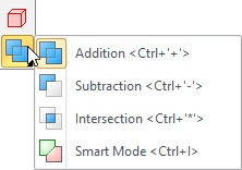
More information about Boolean operations can be found in “Boolean operation” chapter.
Additional Features
Link Dimensions to Existing Geometry
There is possibility to link primitives’ dimensions to the existing geometry.
For this purpose use you need to ![]() on the corresponding manipulator of the parameter and to select a point on the existing geometry using
on the corresponding manipulator of the parameter and to select a point on the existing geometry using ![]() .
.
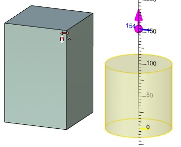
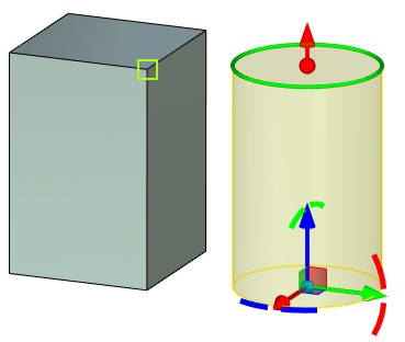
A primitive will transform according to the changes in the linked body.
You can break a link using special option. The option appears near the linked parameter.

You cannot create a link if a source coordinate system of the primitive has been changed using Select or Create source LCS option. Warning appears in this case.
Create Driving Dimensions
You can create driving dimensions for primitive using option Create driving dimensions in the Options section.

Driving dimensions can be created for box, cylinder and prism primitives.
Primitives Group Operations
Unique set of parameters is displayed in the Properties window for each operation from Primitives group
When you change primitive dimensions using 3D manipulators in the scene, corresponding parameters are also changed in Properties window. Value of changed dimension is displayed in the top of the window upon manipulator movement.
![]()
Box
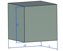
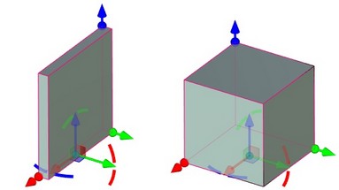
You can set the following box parameters: Length, Width, Height.
When the Cube flag is set only Length parameter field can be changed. You can specify length of all cube sides here.

Cylinder
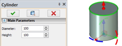
You can specify Diameter and Height for the cylinder.
Cone
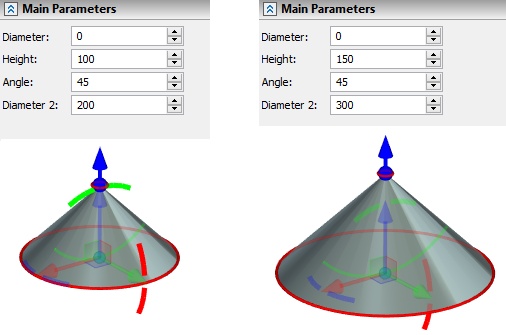
It is available to specify Diameter, Height, Angle and Diameter 2 for the cone. Diameter defines cone apex diameter. Angle and Diameter 2 values depends on each other. Angle value depends on height.
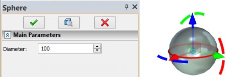
Sphere
You can specify diameter for the sphere.
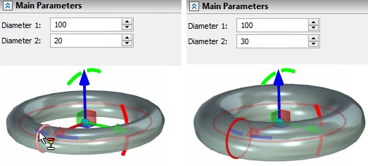
Torus
It is available to specify two diameters for the torus.
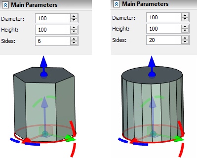
Prism
You can specify Diameter, Height and Sides for the prism. The maximum number of sides is 100.
Pyramid
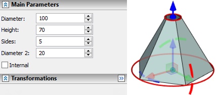
You can specify base diameter, apex diameter, height and number of sides for a pyramid. The maximum number of sides is 100.
