Skew |
  
|
Skew |
|
General Information
In the skew deformation, the deformation function is specified by displacing the vertices of the bounding parallelepiped of the given body. The bounding parallelepiped is calculated with respect to the axes of the global coordinate system or additionally-specified LCS. The offset of vertices of the bounding parallelepiped can be realized along any axis of the coordinate system (the axis with respect to which the bounding parallelepiped is constructed), along the edges of the bounding parallelepiped, along the face diagonals of the bounding parallelepiped. For specifying the offsets in the command, the draggers as well as the dialog of the command's properties can be used. |
|
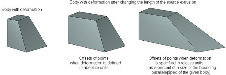
The magnitude of the vertex offset for a bounding parallelepiped can be specified both in absolute units – units of model and in relative units – in fractions of length (in percents) of the bounding parallelepiped along the respective axes. The relative coordinates can be used in cases when it is necessary to preserve proportions of the deformed model no matter what changes in the source operations are made. For example, the picture below shows how the deformed model will be modified when changing the length of the source extrusion depending on in which units the offsets of the vertices of the bounding parallelepiped have been specified.
The vertices of the bounding parallelepiped can be snapped to the 3D points. In this case the offset does not depend on modification of the deformed body or on what units of length have been chosen for specifying the offsets.
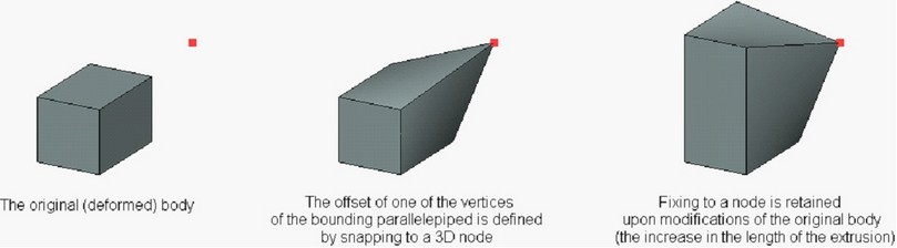
When attaching the vertex to a 3D point, the offsets of the vertex with respect to the selected 3D point can be specified additionally.
Creation of Skew Deformation
Skew deformation is performed with the help of the command “3DRS: Skew Deformation”:
Icon |
Ribbon |
|---|---|
|
3D Model → Special → Deformation → Skew Deformation |
Keyboard |
Textual Menu |
<3DRS> |
Operation > Deformation > Skew Deformation |
For specifying this deformation it is necessary:
1.Select a body being deformed;
2.Define LCS with respect to which the bounding parallelepiped will be formed (optional step);
3.Specify the required offsets of the vertices of the bounding parallelepiped;
4.Complete the operation creation by pressing ![]() .
.
Selection of Deformed Body and LCS of Deformation
For selecting the deformed body, the following option of the automenu is used:
|
<O> |
Select Body to Deform |
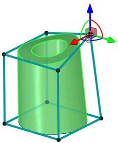
This option is turned on by default upon the entry into the command. The deformed body is selected with the help of ![]() in the 3D window or in the tree of the 3D model. The selected body is highlighted, and the contour of the bounding parallelepiped appears.
in the 3D window or in the tree of the 3D model. The selected body is highlighted, and the contour of the bounding parallelepiped appears.
By default the bounding parallelepiped is calculated with respect to the axes of the global coordinate system. It is possible to select another coordinate system for calculation of the bounding parallelepiped with the help of the option:
|
<L> |
Select source LSC |
After choosing the LCS, the bounding parallelepiped will be automatically reconstructed in accordance with the axes of the LCS.
Cancellation of the selected LCS can be done with the help of the option:
|
<C> |
Cansel LSC selection |
Specifying Offsets for Nodes of Bounding Parallelepiped of Deformation
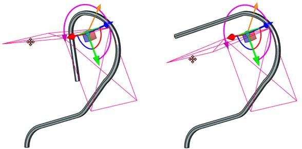
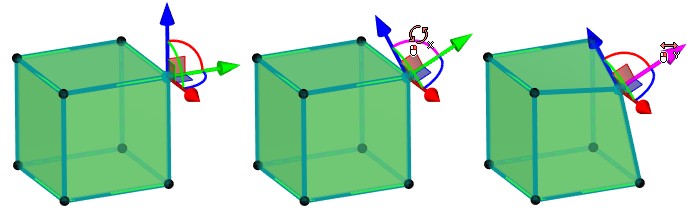
After constructing the bounding parallelepiped, in the 3D window a user can select the nodes of the parallelepiped in any order and specify their offsets (with respect to initial position). To specify the nodal offsets, the 3D draggers are used.
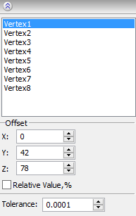
The offsets of the vertices of the bounding parallelepiped (with respect to their initial position) can be also specified in the dialog of the command's properties. After selecting the deformed body, the list of all vertices of the bounding parallelepiped will appear in the dialog. Under the list, there will be entry fields for input of the offset values (the parameters group “Offset”). To specify the offsets, it is sufficient to select the desired node-vertex from the list (it will be highlighted in the list and in the 3D window), and specify the offset values along the axes X, Y, Z in the entry fields of the group “Offset”.
Units in which the offsets of vertices are specified are controlled by the status of the flag “Relative Value, %”. By default this flag is turned off, and the specified offsets are absolute (i.e., are measured in units of model). If the flag is enabled, the specified offsets will be recalculated in relative units.
For fixing a vertex of the bounding parallelepiped to a 3D point, select the desired vertex (in the 3D window or in the list of vertices in the dialog of the command) and turn on the following option of the automenu:
|
<Z> |
Set Fixing to Point |
After activating this option, 3D fixing point has to be selected. The drop down list of this option contains filters for selecting various 3D objects capable of defining a 3D point.
For a vertex of the bounding parallelepiped fixed to a 3D point, the offsets entry fields in the properties window will remain accessible. The offsets specified in these entry fields will determine the vertex offset with respect to the 3D fixing point. The offsets with respect to a fixing point can be also specified in the 3D window with the help of the draggers.
To cancel a fixing to a 3D point, select the desired vertex (in the 3D window or in the vertices list in the dialog of the command) and invoke the following option of the automenu
|
<D> |
Cancel Fixing to Point |
After invoking this option, the vertex is untied from the 3D point. Note that the offset of the given vertex does not change at that. The vertex will remain in the position specified by the 3D point. However, later, when modifying the original model or location of the 3D point, the offsets of the given vertex of the bounding parallelepiped will be recalculated as if they were specified by numeric values from the beginning.
Options in Deformation Operations
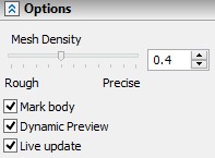
In the process of specifying/editing parameters of deformation, the future result of the current operation is dynamically shown in the 3D window. For speeding up the work, the dynamic preview can be turned off by taking off the flag “Dynamic Preview” in the command's properties window.
An additional parameter “Mesh Density” controls accuracy of the mesh used for visualization of the result of the deformation. The increase in the mesh density leads to slower regeneration of the bodies in the scene but increases accuracy of the drawing. |
|
If you disable option Mark body, the body is no longer highlighted in the scene, which simplifies visual perception of the deformed object.
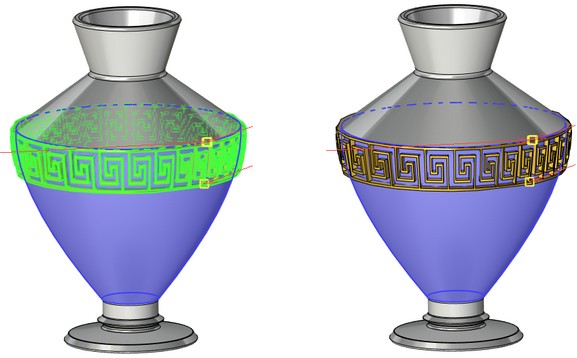
On |
Off |
The Live update option allows to watch deformations of the body in real time. Deactivating the option accelerates recalculation because solid body updating is not required.