Top-down Design |
  
|
Top-down Design |
|
When using the "Top-down" design approach, separate parts-fragments are created directly within the assembly drawing window while working with the assembly. There are two approaches to creating a fragment when using the "Top-down" method - fragment extraction and working in the assembly context. In the first case, a fragment can be created by extracting into a separate file the necessary elements of the assembly drawing. The second case allows creating a new part drawing with the provision for referencing existing elements of the assembly drawing.
The fragments created in this way can be attached to the elements of the assembly itself or other existing fragments. This helps excluding or significantly reducing use of external variables and simplifies handling of an assembly. Meanwhile, some values of the original model parameters can be obtained directly from the assembly context. This approach significantly simplifies relating elements with each other and provides parametric relation between those. If dimensions or position of one of the parts is modified, then all related model elements will adjust automatically.
Working in the assembly context simplifies in certain cases the design process of the assembly module. This also facilitates development of the complete documentation suite of such a module, including detail drawings of all contributing fragment parts. Upon modifications to any assembly document, either the assembly drawing itself or one of its fragments, the changes propagate to all documents of the assembly (automatically or by the user request). As a result, modifications to one part cause update of the full suite of new documentation for the assembly, including the assembly drawing itself and detail drawings of all contributing part fragments.
The "Top-down" design approach may not be suitable in all cases of designing assemblies. The method has certain shortcomings that limit its use:
●More complicated organization, compared with the approach "from part to assembly";
●Lesser robustness to topology changes. For example, once an assembly line is referenced by an introduced fragment, it can no longer be deleted, otherwise the fragment associative reference will be lost;
●This approach is less convenient in terms of reusing fragments in other assemblies, since modifying a fragment may be complicated without the availability of references to the original assembly;
●Upon an attempt to extract a fragment, if it is impossible to "detach" an element from the assembly drawing, additional copies of the necessary elements are created in order to preserve parametric relations in the assembly drawing;
Somewhat higher computational resources are required.
●The icons for handling the "Top-down" approach can be found:
●In the textual Menu "File|Fragment|...";
●In the automenu of the command "FR: Create Fragment":
![]() <C> Create Fragment in Assembly
<C> Create Fragment in Assembly
![]() <G> Mark out Fragment
<G> Mark out Fragment
Managing fragments in assembly context
When using the option ![]() , the first step will be specifying the name of the fragment being created, using the "Save As" dialog box. After that, all construction elements of the assembly will be hidden in the drawing window, and the graphic elements drawn in halftone. While in this mode, all newly created construction and graphic elements will belong to the new fragment. As you create drawing elements, you can use one of the following modes of snapping to assembly elements:
, the first step will be specifying the name of the fragment being created, using the "Save As" dialog box. After that, all construction elements of the assembly will be hidden in the drawing window, and the graphic elements drawn in halftone. While in this mode, all newly created construction and graphic elements will belong to the new fragment. As you create drawing elements, you can use one of the following modes of snapping to assembly elements:
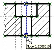
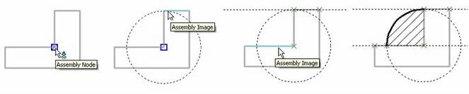
● Associative snapping (the icon ![]() must be in the pushed state). In this case, the fragment elements can be snapped to the graphic lines and nodes of the assembly. (By assembly nodes, we mean the joint points of the graphic lines and the attachment points of the detailing elements.) This ensures two-way relation between the assembly and the fragment file. In other words, changes in the assembly drawing can be propagated, upon the user request, into the fragment file, and, vice versa, modifications in the fragment file cause the assembly document update. As the pointer approaches assembly nodes in this mode, those are highlighted and marked by the tooltip "Assembly Node", while the graphic elements – "Assembly Image".
must be in the pushed state). In this case, the fragment elements can be snapped to the graphic lines and nodes of the assembly. (By assembly nodes, we mean the joint points of the graphic lines and the attachment points of the detailing elements.) This ensures two-way relation between the assembly and the fragment file. In other words, changes in the assembly drawing can be propagated, upon the user request, into the fragment file, and, vice versa, modifications in the fragment file cause the assembly document update. As the pointer approaches assembly nodes in this mode, those are highlighted and marked by the tooltip "Assembly Node", while the graphic elements – "Assembly Image".
● Non-associative snapping (the check box ![]() pushed). In this mode, snapping to assembly drawing elements is also available. However, in this case, snapping is done to the current "snapshot" of the assembly. The future modifications of the assembly lines won't affect the fragment image.
pushed). In this mode, snapping to assembly drawing elements is also available. However, in this case, snapping is done to the current "snapshot" of the assembly. The future modifications of the assembly lines won't affect the fragment image.
● No snapping (both of the above modes should be undone). This mode is none different from conventional drafting. The assembly drawing displayed on the screen does not interact with the fragment elements in any ways.
The icons of the snapping modes can be found in the context menu and also in the textual menu “Customize|Snap|...”.
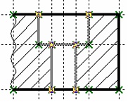
The following diagrams show fragment creation in the assembly context, using associative snapping. In this mode, the assembly construction elements are hidden, while its graphic lines are shown in the halftone. When creating fragment construction lines, snapping to assembly elements is engaged. The graphic elements of the fragment drawing are created last.
Upon finishing working with the fragment, the system returns to the normal mode of working with the assembly drawing. If the created fragment was saved, its image will appear in the assembly. To finish working with a fragment, use the options in the context menu: |
|
![]() <FF> Save Fragment and Return to Assembly
<FF> Save Fragment and Return to Assembly
![]() <FQ> Close Fragment
<FQ> Close Fragment
The option ![]() completes working with the fragment either with saving the results or without saving, at user's choice
completes working with the fragment either with saving the results or without saving, at user's choice
Mark out fragment from assembly drawing
The option ![]() serves for creating a new fragment by moving or copying into a separate file already existing elements of the assembly drawing. Upon the call, the following options appear in the automenu:
serves for creating a new fragment by moving or copying into a separate file already existing elements of the assembly drawing. Upon the call, the following options appear in the automenu:
![]() <End> Finish Fragment Creation
<End> Finish Fragment Creation
![]() <M> Select Mode
<M> Select Mode
![]() <M> Deselect Mode
<M> Deselect Mode
![]() <S> Selector
<S> Selector
![]() <F> Assign Fixing Vector
<F> Assign Fixing Vector
![]() <V> Select Variables for Copying into Fragment
<V> Select Variables for Copying into Fragment
![]() <D> Delete or hide selected elements after creating Fragment
<D> Delete or hide selected elements after creating Fragment
![]() <Esc> Exit command
<Esc> Exit command
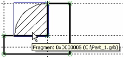
Fragment extraction is the action opposite to that of the option "Explode Fragment". To create a fragment, the user just needs to select a set of graphic elements (lines, dimensions, hatches, etc.) of the assembly drawing to be carried over into the separate fragment. When creating a fragment, besides the graphic elements picked in the assembly drawing, their respective construction elements are also created.
The list of elements available for selection is defined by the option ![]() , that works similar to the command "FT: Set Selector Configuration". The selector settings defined in this option stay active only while selecting elements for creating the fragment.
, that works similar to the command "FT: Set Selector Configuration". The selector settings defined in this option stay active only while selecting elements for creating the fragment.
The option ![]() allows picking the assembly drawing elements, adding those to the contents of the fragment. (The selected elements are highlighted.)
allows picking the assembly drawing elements, adding those to the contents of the fragment. (The selected elements are highlighted.)
The option ![]() excludes elements from the selected set.
excludes elements from the selected set.
The option ![]() toggles between the modes:
toggles between the modes:
●If the icon is in the pushed state, then, after creating the fragment, the elements included in the fragment are deleted from the assembly drawing. Exception is the parent elements of other elements. In this case, the system will not delete the element. Instead, it will make it hidden (invisible) by assigning a special attribute;
●If the icon is not pushed, then the fragment contents are formed by the copies of the selected elements.
Creation of a fixing vector (the option ![]() ) is optional. However, if you need to make a provision for modifying the attachment of the fragment being created or placing its duplicate at other locations, then you should perform this step. A fixing vector can be created in one of the ways described above.
) is optional. However, if you need to make a provision for modifying the attachment of the fragment being created or placing its duplicate at other locations, then you should perform this step. A fixing vector can be created in one of the ways described above.
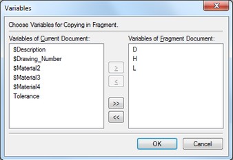
The option ![]() brings up the dialog box for selecting variables existing in the assembly drawing, to be copied to the fragment. The list in the left-hand side pane contains all plain variables. Variables defined by an expression cannot be copied into a fragment. The variables can be carried from the left to the right pane and back using the graphic buttons [>], [<]. The buttons [>>], and [<<] allow carrying over the whole list. All fragment variables that originated from the assembly drawing are automatically deemed "external".
brings up the dialog box for selecting variables existing in the assembly drawing, to be copied to the fragment. The list in the left-hand side pane contains all plain variables. Variables defined by an expression cannot be copied into a fragment. The variables can be carried from the left to the right pane and back using the graphic buttons [>], [<]. The buttons [>>], and [<<] allow carrying over the whole list. All fragment variables that originated from the assembly drawing are automatically deemed "external".
The fragment creation can be completed using the icons:
![]() <End> Finish Fragment Creation
<End> Finish Fragment Creation
![]() <Esc> Exit command (without saving the fragment)
<Esc> Exit command (without saving the fragment)
Calling the option |
|
After that, a fixing vector is created. Next, the necessary variables are selected, and the filename is defined. As a result, the selected lines are placed in the assembly drawing by the 2D fragment possessing the set of the specified parameters. Whenever possible, we recommend creating all elements directly in the new fragment, rather than carrying those over from the assembly drawing. This approach enhances productivity. |
|