How 3D Fragments Work


How 3D Fragments Work |
  
|
In the approach "from part to assembly", the assembly is composed of 3D fragments. In this case, it is implied, that the bulk of work on creating the part model is already done, and what is left is just assembling it. The main steps for assembling a 3D fragment are as follows:
1. Select the 3D model file to use as the 3D fragment.
2. Attach the 3D fragment to the assembly model.
3. Define the values of the fragment external variables and parameters.
Next, let's review the main concepts of 3D fragment insertion.
Relation between assembly and 3D fragment file
There are two ways of selecting a 3D model file. The first is by explicitly selecting the model file. The second way allows using the existing 2D fragments within the assembly drawing, that have the respective 3D models. This is possible in the case when the 2D fragments were already used in the current document, as, for instance, for initial creation of the drawing assembly.
The system always maintains the relation between the 3D fragment file and the assembly file. The assembly file keeps, among each 3D fragment parameters, the reference to the 3D fragment file. T-FLEX CAD automatically tracks changes in the 3D fragment files. If necessary, it reloads the 3D fragment data into the assembly. To do this, the 3D fragment is searched using the store the reference. The reference path to the fragment file can be full or relative. To provide greater system flexibility, especially when porting models from one file system to another, we recommend using relative paths for the references. When writing the relative paths, the assembly file and its location in the file system are used as the guide. Another way of creating relative references relies on library configurations.
Fragment with variable reference
Just like in the case of using 2D fragments, a textual variable can be used as the reference path for 3D fragments being assembled. The value of such variable is the path to the file of the currently used 3D fragment. Depending on some conditions, this value can vary, becoming the reference to a different 3D fragment file. This allows creating assemblies with changing elements. There is one limitation on use of 3D fragments. All 3D fragments used in this scheme must have the original coordinate systems with the same name or be defined in the world coordinates.
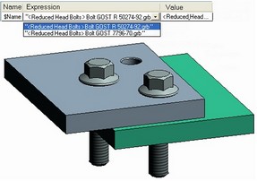
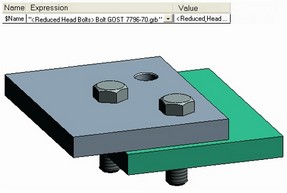
3D fragment attachment
To insert a 3D fragment model in the assembly model, you need to decide on the attachment. Attaching a 3D fragment means defining two coordinate systems – the source and the target one. One of the systems belongs to the 3D fragment, while the other - to the assembly. The 3D fragments geometry positioning is fully defined in the space upon placing the source coordinate system over the target one. The source and the target coordinate systems are usually represented by assigning or explicitly creating a Local Coordinate System (LCS) at the time of assembling the 3D fragment. If no LCS is specified, then the World Coordinate System is used instead.
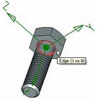
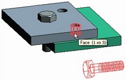
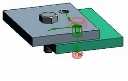
Create source LCS by selecting edge. Create target LCS by selecting cylindrical face.
In complicated cases, when fixing by coordinate systems cannot provide correct positioning of a 3D fragment, we recommend using Mates mechanism (see below the detailed description of the Mates mechanism).
There is yet another way of defining the position of the 3D fragment based on the 2D fragment. This is a technique called "layout". In this case, the 3D fragment orientation is done according to the 2D fragment fixing vector. The fixing vector must reference a workplane. This results in two coordinate systems. The source system is defined based on the fixing vector and its related workplane in the fragment document. The target coordinate system will be defined based on the final position of the fixing vector in the page of the assembly drawing and the selected workplane.
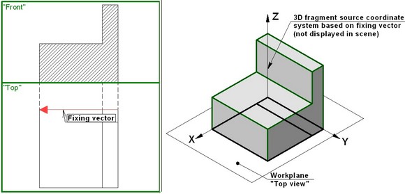
The X-axis of the coordinate system coincides with the fixing vector and lies in the workplane. The Z-axis is normal to the workplane. The Y-axis is the cross product of the two. In this way, no new LCS is created for attachment. The three-dimensional data for the 3D fragment are loaded from the same 2D fragment file. This means, the 2D fragment is used for creating the plan (the drawing), while the 3D fragment - for building the three-dimensional model. This technique is convenient in some special design cases, when you need to place several three-dimensional objects on one level (plane). This can be, for instance, the task of placing furniture in premises or equipment in a workshop. The three-dimensional objects placing can be controlled in this case directly from the drawing by moving the respective 2D fragments in the plan.
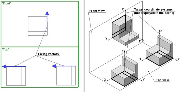
If the 2D fragment is created on a page without workplane, then the system will automatically perform the transformation for carrying the X-axis over the page of the selected workplane. Meanwhile, the fixing vector can be thought of as if carried over the page of the workplane with the same coordinates in the page as it had in the original page of the document. Further constructions are done as usual.
This capability can also be successfully used when creating common assembly drawings. The following diagram shows a trivial model based on a two-dimensional assembly, whose fragments were attached using the fixing vectors. No coordinate systems for attaching 3D fragments were created in the fragment files. Neither were target coordinate systems created in the assembly drawing. The model was created by using the 3D layout technique. Try to realize the steps of building this model independently, in order to check your understanding of this paragraph.
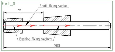
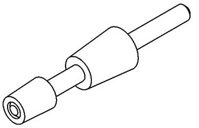
This drawing can be found in the folder "\Examples\3D Assembleis\3D Fragments\Assembly 3.grb".
.
Additional Transformations
Every 3D fragment can use Additional transformations as an auxiliary tool for making fragment location more precise or, in some cases, even as an independent positioning type. These transformations represent themselves translations along the coordinate axes of the insertion coordinate system and rotations about these axes. The value of any additional transformation can be defined via constants, variables or expressions as well as by snapping to geometric objects of a 3D model.
3D fragment variables
Parametric relations of a 3D fragment are controlled by its external variables. When regenerating a fragment, the required geometrical relations and data are loaded from the original file first, then the values of the external variables are copied from those stored in the assembly for this fragment, and, after that, the regeneration starts. Thus, the original file stays unchanged. The same assembly document may have several instances of the same 3D fragment with unique sets of values of the external variables. For example, the same bolt can be used in the assembly with different diameter and length.
Using 3D connectors
3D connector is a special type of LCS which lets us automatically link external variables for jointed parametric elements of assembled 3D models. Connectors significantly simplify parts positioning and fitting of parameters upon design of the assemblies. When a 3D fragment is attached to a 3D connector, the values of the variables are automatically transferred from the connector to the fragment model, which is followed by model regeneration. Preliminary image of a 3D fragment immediately takes the sizes corresponding to the values of the 3D connector variables.
For example, a nut М10 needs to be put on a bolt M10. When the bolt of size M10 is inserted into the assembly, its connector automatically remembers this diameter. Upon insertion of the nut, a required connector for attaching the nut is automatically chosen at the moment when the bolt elements are being selected. For a variable taking over the nut diameter, instructions are given – ask the connector the value of the variable. If the names coincide, the bolt connector passes the value М10 to the nut. Thus, right after connector selection, location, parameters and image of the nut are brought in accordance with the required bolt.
A user can create 3D connectors independently while preparing the 3D fragment model (See section “Local Coordinate Systems”). The elements of service libraries and standard parts, supplied with the system (Fasteners, Holes etc.) already have embedded 3D connectors.
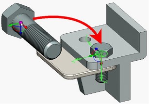
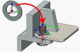
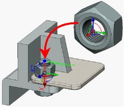
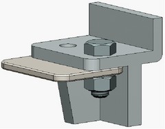
Insertion rules, which remain active upon selection of the given connector in the assembly for attaching the fragment, can be defined for a 3D connector. The insertion rule is a mandatory additional way of defining fragment location by moving it along one of the coordinate axes or by rotating it with respect to the axis (see “Additional transformations”).
External geometrical parameters of a 3D fragment
External parameters of a 3D fragment can be not only external variables, but also geometrical elements (a solid, 3D node, 3D path, 3D profile, workplane, LCS, vertex, edge, face, loop). Such 3D fragment is called adaptive. Normally, such 3D fragments are most often used for direct modeling (grooving, drilling nonstandard holes and similar elements), rather than for creating assemblies; therefore, all information related to handling adaptive 3D fragments is separated into a dedicated section in this book (see the chapter "Adaptive 3D fragments").
Using 2D-fragment as «projection» for 3D fragment
●It is possible to insert 2D fragments that present projection of corresponding 3D fragment. This mechanism of operating with assemblies is useful when designing plans to deploy industrial equipment. It helps you to create drawings of floor plans, plans of rooms, etc.
●To create a 2D fragment as projection of the existing 3D fragment you have first to specify workplane when creating a 2D fragment. This workplane helps to position future 2D fragment correctly. Then after selecting 3D fragment that will be used as source for the new 2D fragment you need to define the type of presentation for this 2D fragment. This may be done in «2D Projection» dialog where you can chose either type of projection or fixing vector associated with some predesigned 2D drawing. In case of fixing vector it must follow condition of correspondence to the workplane selected on the first step. In case of projection it will correspond to direction defined by the workplane. As result you will get the 2D fragment that will match source 3D fragment. Location of both fragments (2D and 3D) will be interdependent.
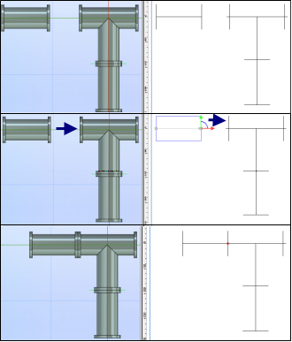
Relation between 2D and 3D fragments.
When inserting a new three-dimensional fragment, the system always creates the respective 2D fragment referencing the same file. There is always an inherent relation between the 2D and 3D fragments. Both fragments use the same data related to variable values, as well as some settings – the file name, the way of including in a BOM, the status settings. Usually, the 2D fragment is not necessary when creating a 3D assembly model; therefore, the system hides it by default. The 2D fragment can be selected only by using the dedicated command for editing 2D fragments. Using this command may be convenient, for example, when you need to modify a bulk of references to fragment files, since the command provides convenient tools for simultaneous management of lists of the fragments. A 3D fragment document may contain the two-dimensional drawing along with the three-dimensional geometry. This drawing can be used for automatic creation of the assembly drawing, by following certain rules. In this way, the image of each 2D fragment will be put in the first page of the assembly document with the same page coordinates as those of the image in the original file.
Using dimensions of fragments in assemblies
3D dimensions drawn inside the fragment’s document can be “raised” into the assembly. To do so, in the window of properties of the command of dimension creation/editing, on the “General” tab, it is required to enable the “Show on 3D fragments” flag. Dimensions raised to the 3D assembly from fragments can be used for two purposes: ●As decorative – they show the value of the dimension; |
|
●As controlling – these dimensions are used for specifying the values of external variables of the fragment by means of editing their nominal value. To do so, in the dimension’s parameters it is required to select the value’s type “Manual”, and write the external variable name in the expression’s field. Editing the value of such a dimension in the assembly will be accessible both when the 3D fragment editing command has been launched and via the usual scheme of the change of controlling dimensions in the “Set dimensions’ value” command.