Body Taper


Body Taper |
|
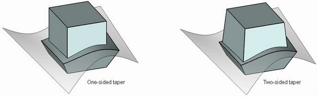
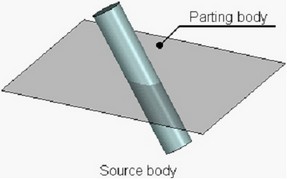
Body taper operation allows the user to create two-sided tapers of faces of a body relative to a specified taper direction and a parting body. A parting body divides the original body into two parts: “top” and “bottom”, which are tapered with respect to each other. A sheet body is usually specified as a parting body, but solid bodies can be used as well.
For “top” and “bottom” tapers, the operation enables specifying different taper angles. If necessary, it is possible to specify only “top” or “bottom” angle, that is, create a one-sided taper of a body.
The use of body taper operation allows the user to significantly simplify the process of designing cast parts and their molds. The parting body corresponds to the surface of separation, and the taper direction - to the direction of the mold separation.
General concepts and operation capabilities
General Concepts
For creating a body taper, first of all it is necessary to indicate a tapered body itself, a parting body, the sets of “top” and “bottom” fixed edges of the tapered body, taper direction and angle.
Taper Direction
Taper direction is an oriented in space vector, relative to which the taper angles of the faces will be measured.
Taper direction vector can be defined by two methods:
●by one 3D object whose geometry can define a vector;
●by two 3D points defining the start and end points of a vector.
Parting Body
A parting body is used for dividing the original body into two parts, each of which can be tapered individually. When tapering faces at both sides from the parting body, a two-sided taper is created. When tapering faces located at one side from the parting body, a one-sided taper is created.
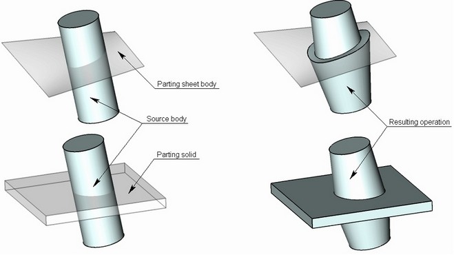
Both sheet and solid bodies can be used as a parting body. In most cases, a sheet body is used as a parting body. After executing the operation, a parting body is remained in the 3D scene.
The parting body may not have through holes. Additionally, the parting body must be large enough to fully intersect the target body in the taper direction.
If a solid was selected as the parting body, then use of the “Body Taper” operation will result in one body obtained by merging the tapered and the parting body.
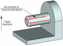
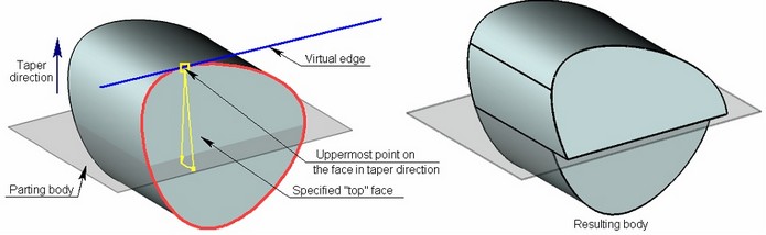
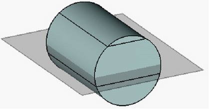
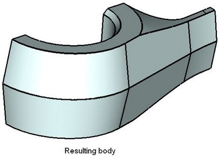
The source body itself can be used as the parting body. On the figure below, an isoclinal line of the faces of the original body was selected as the source edges for creating the taper. The original body itself serves as the parting body.
Fixed Edges/Faces
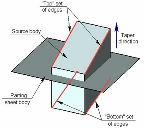
For creating two-sided tapers of a body it is required to specify two sets of edges: “top” edges and “bottom” edges.
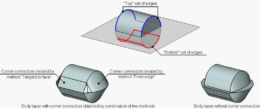
The so-called “top” and “bottom” sets of base edges are respectively those located above and below the "parting body", with respect to the taper direction. The edges define the faces for which a taper needs to be created, and also define the fixed lines of these faces.

It is possible to select only one set of fixed edges (“top” or “bottom”). In this case, a one-sided taper will be created.
Instead of source edges, the user can specify the source faces themselves. For example, when creating a body taper, it might be impossible to select base edges of the “top” and “bottom” sets. Those edges might either not exist, or have the geometry that would not allow creating a body taper. In this case, for creating a taper the user indicates the sets of source faces based on which the virtual edges for constructing the body taper are defined. If, for example, a face was selected as “top”, then the command will automatically find the uppermost point on this face with respect to the taper direction. A virtual edge is defined at this point, passing tangentially to the edge of the selected face and perpendicular to the taper direction vector.
Taper Angle
Taper angle is specified separately for the “top” and “bottom” set of edges, i.e. for the “top and “bottom” faces. Within each set, all faces will have identical taper angle.
Corner Connection
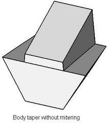
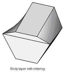
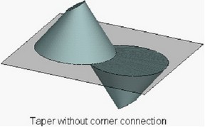
As a result of performing a two-sided taper, along the line separating the tapered faces of the body, a gap-step can be created due to non-uniform displacement of the “top” and “bottom” faces. It is possible to avoid creation of this step by using the mode of corner connection.
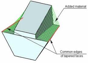
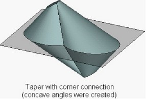
When creating an corner connection, the system automatically adjusts the displacements of the “top” and “bottom” tapered faces in such a way that they have a common edge (on the parting body). Correction of displacements is always carried out by adding material.
An corner connection can be created only upon constructing a two-sided taper with the sheet parting body.
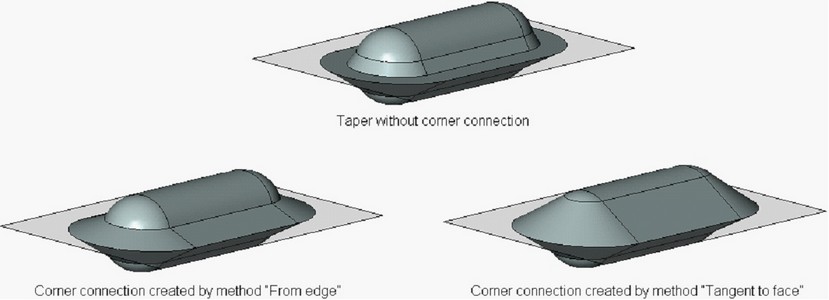
Creating the corner connection can be performed by one of the following methods:
● “From edge” – the material is added from the edge determining the given face. The boundaries of the corrected face will include the source edge specified for this face (or a part of the edge);
●“Tangent to face” – the material is added in such a way that the corrected surface becomes tangent to the adjacent faces (where it is possible). Simultaneously, the original edges may be deleted and replaced with the new edges created on the basis of the line of intersection of the corrected face and adjacent face;
●Combination of first two aforementioned methods – depending on the geometry of the resulting body, the system itself selects the method of creating the corner connection for each tapered face needing the correction. Priority is given to the method “From edge”. If, for some face, this method cannot be used, another method “Tangent to face” is employed.
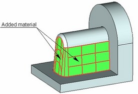
On the figure below, an example of creating an corner connection with the use of combination of two methods is shown. The “top” set of taper edges is non-closed, and it is impossible to employ the method “From edge” for the lateral cylindrical face. Thus, for creating a corner connection on the lateral faces of the tapered body, the method “Tangent to face” was used. On the end faces, the correction is carried out by the method “From edge”.
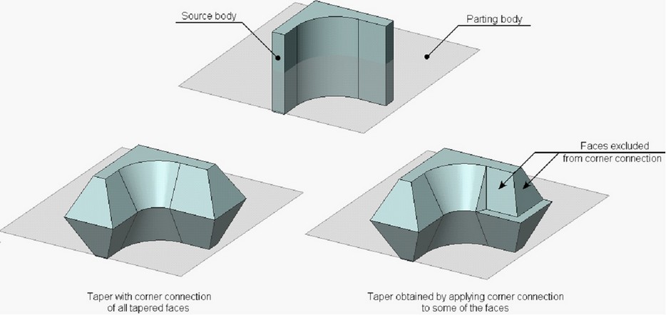
By default, in the mode of corner connection, the system adjusts the displacements of all tapered faces. If necessary, it is possible to suppress the displacement correction for any of the tapered faces.
Taper creation method
The following methods of creating the body taper exist in the command:
●“Standard” – allows constructing the taper surface exactly matching the form of the source surface and a specified taper angle.
●“By curve”, “By surface” – matches the form of the source tapered faces in a less stringent manner, which allows constructing the taper in cases when the standard taper construction method does not work.
These algorithms are described in more detail in chapter “Face Taper”.
By default, the standard taper creation method is used in the operation. If necessary, it is possible to apply another method of tapering to the entire tapered body as well as to each tapered face individually.
Concave Edge Correction
In some cases while creating the taper with the corner connection, concave angles are created on the body, which can interfere with successful creation of taper operation.
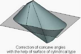
To avoid such a situation various methods of processing the concave angles exist in the operation:
●No correction – created concave angles remain unchanged;
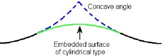
●Cylindrical surface – concave angles are “covered” with a surface of cylindrical type. Simultaneously, in the plane of a parting body the projection of the concave angle is replaced with the circular arc of specified radius. |
|
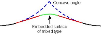
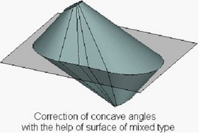
●Mixed surface – the concave angles are “covered” with the surface of mixed type. In the plane of a parting body, the projection of an angle is replaced with a circular arc of a given radius and lines tangent to the surface of the tapered body. |
|
Processing Connections of Tapered Faces
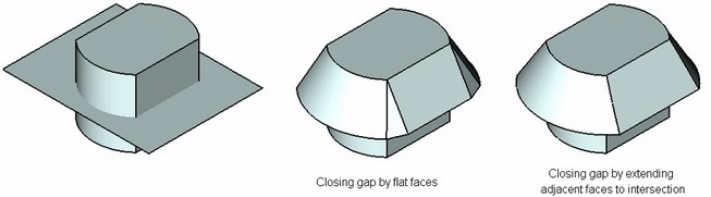
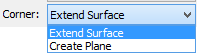
When creating a taper, the command provides options for selecting a method of processing connections between tapered faces. Two processing methods are available:
●Extend surfaces – in this case, the adjacent tapered faces will be extended to achieve an intersection.
●Create plane – in this method, a flat face will be created between two adjacent tapered faces.
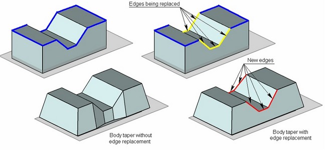
Edge Replacement
In some cases, keeping the shape of edges defined as fixed leads to creation of redundant faces on the tapered body. To improve results of the operation, the user can allow replacement of certain “fixed” edges. Use of edge replacement guards in some cases from creation of extra tapered faces. The replacement edges are created in such away as to make a single slanted face.
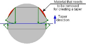
Taper with Undercut
In some cases, creation of a taper requires not the addition but the removal of the material of a tapered body. In this situation, it is necessary to use the option of creating an undercut. Otherwise, creation of a taper will be impossible.
Body taper creation
The "Body Taper" command can be called by one of the following means:
Icon |
Ribbon |
|---|---|
|
3D Model → Modify → Body Taper |
Keyboard |
Textual Menu |
<3TB> |
Operation > Taper > Body Taper |
To create a body taper, do the following steps:
1.Select the source body.
2.Select the parting body.
3.Define the taper direction.
4.Select the top set of edges.
5.Select the bottom set of edges (required for the two-sided taper).
6.Define the top and bottom taper angles.
7.Define additional parameters of a taper (the method of creating a taper, the method of processing connections between tapered faces, an corner connection, etc.);
8.Complete operation creation with the help of ![]() .
.
Main Input Data for the Operation
Selecting source body
The default mode of selecting the source body is activated automatically upon entering the “Create Body Taper” operation:
![]() <S> Select source body
<S> Select source body
This source body can be selected either in the scene or in the 3D model tree. After selecting the source body, the properties window will display the respective operation of the source body.
Selecting parting body
Upon selecting the source body, the system proceeds to the mode of selecting the parting body. To enable selection of a solid or sheet as a parting body, the following options are provided in the command automenu:
![]() <P> Select parting body
<P> Select parting body
![]() <H> Select parting sheet body
<H> Select parting sheet body
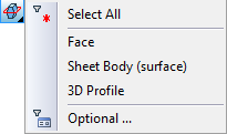
When using one of those options for selecting the parting body, the selector is tuned up accordingly. For example, in the sheet body selection mode, the following parting objects can be selected: a face, a 3D profile, an operation-surface. Moreover, filters for choosing the objects can be also customized with the help of the drop-down list of the option In the solid body selection mode, only objects with solid geometry can be selected for parting. |
|
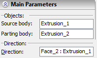
The name of the object used as the parting body appears in the properties window.
Defining taper direction
The next step in the operation creation is selecting an element defining the taper direction. This can be done by the option:
![]() <D> Set tapering direction
<D> Set tapering direction
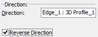
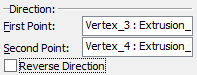
As common across other operations, the option for selecting the taper direction allows selection of various 3D elements capable of defining a directional vector. The direction-defining object is displayed in the properties window. To change the taper direction to the opposite, check the parameter “Reverse Direction”. |
|
Alternatively, the taper direction can be defined by two 3D points. The following options are provided for this purpose:
![]() <1> Select first point of tapering direction
<1> Select first point of tapering direction
![]() <2> Select second point of tapering direction
<2> Select second point of tapering direction
Selected elements are displayed in the “Properties” window.
To cancel the direction selection, use the option:
![]() <K> Cancel direction selection
<K> Cancel direction selection
Selecting fixed edges
Selection of the set of edges is done directly in the 3D window. To create a one-sided taper, select just the top set of edges. For the two-sided taper, additionally select the bottom set of edges. To do this, use the following options:
![]() <T> Select top edges
<T> Select top edges
![]() <B> Select bottom edges
<B> Select bottom edges
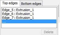
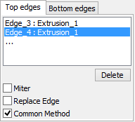
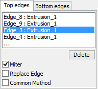
Each selected edge will be added to the list of edges in the properties window. Switching between selecting the top and bottom sets of edges can be done either by the automenu options or by clicking the respective tabs in the properties window dialog. To remove an edge from the list, select it in the list, and then press the [Delete] button or <Del> key. |
|
Options ![]() and
and ![]() can be used in combination with the mode of selecting a sequence of smoothly connected edges, which can be activated by the option:
can be used in combination with the mode of selecting a sequence of smoothly connected edges, which can be activated by the option:
![]() <G> Smooth edge chain selection mode
<G> Smooth edge chain selection mode
Let us define a sequence of smoothly connected edges as a set of edges forming closed or non-closed continuous curve which does not have sharp turns (the first derivative is continuous).
When using the given mode, all edges capable of making a smooth sequence with the chosen edge are automatically picked.
To cancel selection of all edges, use the following option:
![]() <R> Cancel selection of all edges
<R> Cancel selection of all edges
Selecting non-fixed faces
The following options are provided for selecting bottom and top faces:
![]() <U> Select top faces
<U> Select top faces
![]() <O> Select bottom faces
<O> Select bottom faces
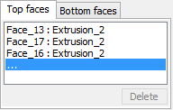
You can activate selection of top or bottom faces by clicking an empty line on the respective tabs of the “Top and Bottom Faces” section in the properties window. Selection of faces, just like edges, is done in the 3D window. The selected faces will be added to the list of faces in the properties window. To remove a face from the list, select it in the list, and then press the [Delete] button or <Del> key. |
|
To cancel selection of all faces, use the option:
![]() <Z> Cancel selection of all faces
<Z> Cancel selection of all faces
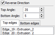
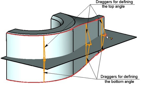
Defining taper angles
The command allows defining taper angles for the top and bottom faces of the source body. The angles can be defined by specifying values in the properties window. To modify taper angle values, you can also use draggers. Once the edges are defined, with respect to which the body taper will be constructed, the draggers appear in the 3D window for modifying the angles. Those draggers work the same way as the draggers defining taper angles in the command “3TA: Create Face Taper”. |
|
At this stage, the option becomes available in the automenu:
![]() <Y> Finish input
<Y> Finish input
Advanced Operation Parameters
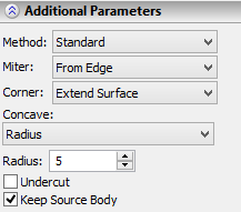
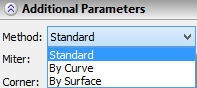
Selecting Method of taper creation The method of creating a taper is determined by the value of the parameter “Method”. To change the value of this parameter, a drop down list is used. The standard method is used by default. For all selected fixed taper edges the flag “Common method” is set by default. This means that the value of the parameter “Method” is unique for all selected fixed taper edges. When changing the value of this parameter, the taper creation method is changed for all tapered faces. To specify for some tapered face another tapering method (different from the one specified for the rest of the body) it is required: from the list of edges to select the edge corresponding to the given face, turn off the flag “Common method”, and with the help of parameter “Method” specify the required taper method. |
|
|
Creating corner connection
Parameter “Miter” controls creation of corner connection. By default, it is assigned the value “No”, which signifies that the corner connection is not creatred.
In order to create a corner connection, the user needs to select one of the following values: “From Edge”, “Tangent to Face”, or “Both” from the drop down list. Difference between these three options was described above.
A corner connection can be created only upon constructing a two-sided taper with the sheet parting body.
By default, the corner connection is created for all tapered faces of the body. To exclude any of the faces from the corner connection, the user needs to select the edge corresponding to the given face from the list, and, for the selected edge, take off the flag “Miter”.

Selecting Method of Correcting Concave Angles
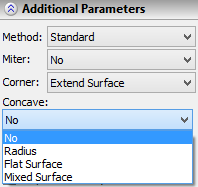
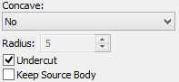
Parameter “Concave” is responsible for correcting concave angles arising upon creation of a taper with a corner connection. By default, this parameter is assigned the value “No”, which means that concave angles remain intact. For automatic correction of concave angles it is required to select another value from the drop down list: -Radius – a concave angle is covered with a surface of cylindrical type. In addition, the radius of the surface must be specified in the parameter “Radius”; -Mixed Surface – a concave angle is covered with a surface of mixed type. The radius of cylindrical segment of the surface is specified with the help of the parameter “Radius”. |
|
Controlling Edge Replacement
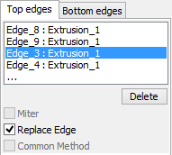
The flag “Replace Edge” controls the capability of replacing fixed edges upon creation of taper. By default, replacement of all selected taper edges is suppressed (flag is turned off for all edges). To permit replacement of any of the edges, the user should select it in the list of edges and set the flag “Replace Edge”. |
|
Closing gaps between adjacent faces
The method of processing the connection between tapered faces is selected with the help of parameter “Corner”.
Specifying Undercut
The mode of creating an undercut is activated with the help of the flag “Undercut”. By default, this flag is turned off.
Keep source body
The operation of creating the body taper allows the user to keep the source body in the 3D scene. For that, it is sufficient to set the flag “Keep Source Body”.