Convert Solid to Sheet Metal


Convert Solid to Sheet Metal |
|
To convert a body into sheet metal SMS: Convert Solid to Sheet Metal operation is used. To call the operation:
Icon |
Ribbon |
|---|---|
|
Sheet Metal → Convert Solid to Sheet Metal |
Keyboard |
Textual Menu |
<SMS> |
Operation > Sheet Metal > Convert Solid to Sheet Metal |
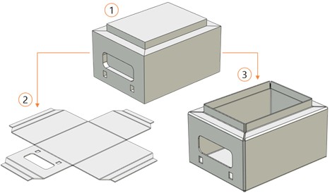
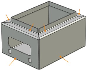
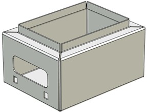
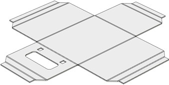
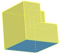
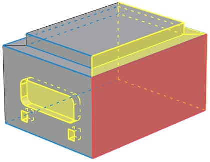
Convert Solid to Sheet Metal operation is used to quickly create bodies or unfoldings from sheet metal basing on solid bodies. The result of Convert Solid to Sheet Metal operation is sheet body unfolding or a sheet part preserving the shape of the initial object.
|
1 – solid body, 2 – sheet part unfolding, 3 – sheet part |
Operation description
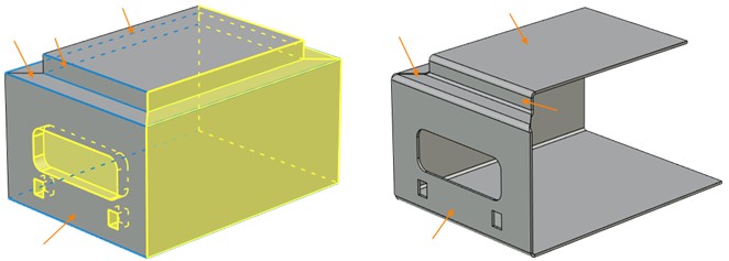
Solid bodies with flat faces can be used as initial bodies for the operation.
Stationary face
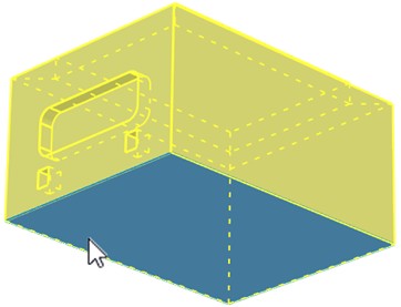
Body unfolding takes place relative to the first face chosen which is considered fixed and determines the unfolding plane position. This face is called stationary face.
Any flat face of the body can be chosen as stationary one. The edges for folding that will be involved in the operation are set relative to it. Stationary face is highlighted blue after being selected.
|
Stationary face selection |
Edges for folding
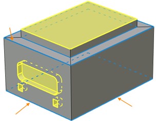
After the stationary face is selected it is time to select edges for folding. The first of the selected edges must be one of the stationary face edges. After the edge is selected the second of the faces building it gets involved in the operation. The moment it is done, you can select other edges of this face as folding edges. Therefore to select a face you need to select at least one of adjoining edges. Further on when building a sheet body a bend will be created at the selected edges, whose radius value is specified in the operation parameters.
All the faces which the selected edges refer to are highlighted gray. The faces which are not involved in the operation are highlighted yellow.
|
|
Selected edges are highlighted blue |
Selected faces |
When selecting the edges, you should make sure that there are no collisions between the sheet elements obtained. This is because it is impossible to obtain a self-crossing flat template with the help of this operation.
Adding thickness
An equidistant surface at a given distance equal to the specified thickness is created for every selected face. The new surface is built inwards, outwards or symmetrically depending on the variant chosen in the parameters window.
|
Outside |
|
Inside |
|
Symmetric |
After finishing the operation all the selected faces are converted into sheet metal and the faces not selected are deleted.
|
Selected faces are gray, deleted ones are yellow |
By default, all the faces highlighted yellow will be deleted when the operation works. If it is necessary to delete a selected face, <D> Select removable faces option is used. The selected face is added into Removed Faces tab of the Operands group in the parameters window and is marked red if selected in the list. In order to cancel face selection for deleting, switch to Removed Faces tab of the Operands group, select the face and press Delete. The button is to the right from the faces list.
Operation parameters
Thickness enables users to set thickness of the obtained sheet metal. Thickness direction can be specified. The following modes are available: inwards, outwards, symmetrically.
|
|
|
Inwards |
Symmetrically |
Outwards |
Radius enables users to specify the rounding radius of sheet metal faces. It is general for all the commands of sheet metal working.
Neutral factor determines the way to specify neutral layer coefficient. It is general for all the commands of sheet metal working.
Radius, Neutral factor and Thickness are taken into account when calculating unfolding length by bending radius arc.
Remove bend edges. An absolutely smooth sheet body is created in the places of bend. When the option is active, Bend Result operation is not executed.
Keep source body. The initial body is added to the current operation result. The option is useful for evaluating how the bended part is inscribed in the initial body dimensions.
Corner group combines general commands parameters of sheet metal working and are described above.
The following automenu options are available:
|
<Ctrl+Enter> |
Finish input |
|
<P> |
Set entity Parameters |
|
<X> |
Exit command |
|
<F5> |
Preview Operation Result |
|
<K> |
Select fixed face |
|
<R> |
Cancel Selection |
|
<B> |
Select bend edges |
|
<D> |
Select removable faces |
|
<E> |
Edit rip edges |
|
<2> |
Change relief type to square at selected vertex |
|
<C> |
Bend result |
Finish input. To build geometry according to the given parameters. In case the parameters are insufficient, the option in not available.
Set entity Parameters. Calls a standard 3-D design command parameters dialog.
Exit command. Shuts down the command cancelling the given parameters.
Preview Operation Result. Enables/disables a standard option for reviewing 3-D design commands.
Select fixed face. Selects the stationary face relative to which the operation proceeds.
Cancel Selection. Cancels selection of all the faces and edges involved in the operation. The option returns to the operation start. It is necessary to select a stationary face and edges again. All the values specified in General Parameters tab (thickness, radius etc.) stay the same.
Select bend edges. Selects the edges by which bending radius will be built. After activating it is necessary to select the edges bordering with the faces involved in the operation starting with the stationary face edges.
Select removable faces. Removes faces from the operation. After selecting the faces involved in the operation you can activate this automenu option and specify the selected faces to be removed as the result of the operation. The edges adjoining the removed faces become unavailable for selection.
Edit rip edges. Enables users to select the edges for changing the gap and overlap type separately. You should choose an edge joining two faces involved in the operation. In the center of the selected edge there will be a marker consisting of two fields: overlap type switch icon and gap input field icon. Overlap types are switched in series by clicking ![]() on the overlap icon.
on the overlap icon.
|
|
|
Overlap |
No overlap |
Reverse overlap |
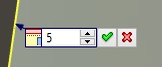
When clicking ![]() on gap icon an input field appears.
on gap icon an input field appears.
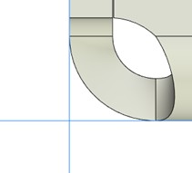
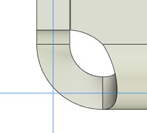
Change relief type to square at selected vertex. Sets weakening at the given vertex. Weakening type can be changed to other than the default one at the selected vertex. By default all the vertices have round weakening. Weakening type can be chosen from a drop-down option list before selecting the vertex: Change relief type to square at selected vertex or Change relief type to welding at selected vertex.
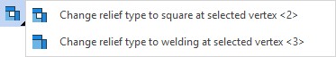
After you choose the vertex a special marker appears near it. The type set for the vertex can be changed by clicking ![]() on the marker.
on the marker.
|
|
Square |
Welded |
To cancel the change of weakening at a vertex, select the vertex again. If there is no special marker of weakening change at this vertex, a default weakening of Round type will be created.
Bend result. Enables/disables an additional command - Re-bend. If the option is enabled, the sheet body preserves the initial object shape. If the option is disabled, the sheet body will be unbent and unfolding will lie in the plane set by the stationary face.
|
|
Sheet part (Bend result enabled) |
Sheet part unfolding (Bend result disabled) |
After finishing the operation with Bend result option enabled, another operation - Re-bend – will appear in construction tree, in addition to unfolding.
In case of properties change in an operation which was already created, Bend result automenu button becomes unavailable. The reason for that is to preserve the logic of operations sequence in case there are other operations in 3D Model window after Unbend.
Creating the operation
A typical procedure for creating the operation is as follows
●To select a stationary face of the body
●To set sheet material thickness and rounding radius of the faces, otherwise they will be set from parameters by default
●To select the edges involved in the operation
●To enable/disable the options: bend result, flat body, initial body (if necessary)
●To set additional operation capabilities: weakening type, overlap type, gap between adjoining edges (if necessary)
●To finish input.
Example of operation work
Using Convert Solid to Sheet Metal operation is demonstrated in the example. Besides, a case when it is necessary to change bending procedure is considered.
Enter sheet metal parameters:
Keyboard |
Ribbon |
Icon |
|---|---|---|
<SMP> |
Sheet Metal → Default |
|
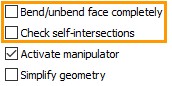
Remove the flags from Bend/Unbend face completely and Check self-interactions options. Now in case of self-intersections of metal sheets the system can show the body obtained this way at the screen. If you leave the flags, the system will not be able to show the self-intersecting body and will display an error.
To create Convert Solid to Sheet Metal operation, call the following command:
Keyboard |
Ribbon |
Icon |
|---|---|---|
<SMS> |
Sheet Metal > Convert Solid to Sheet Metal |
|
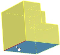
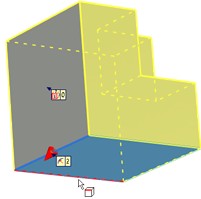
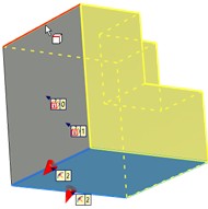
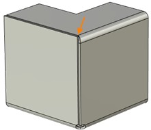
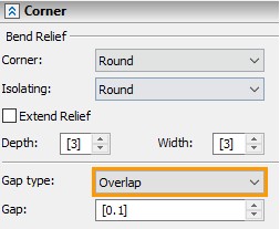
The selection sequence of construction elements to create the operation is shown in the picture below. First, a stationary face is selected. Then three edges of the body are selected in turn. Before executing the operation it was specified in the Corner tab in the parameters window that sheet edges must overlap.
|
|
|
Selecting stationary face |
Selecting first edge |
Selecting second edge |
|
|
|
Selecting third edge |
Result |
Result |
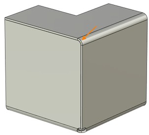
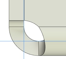
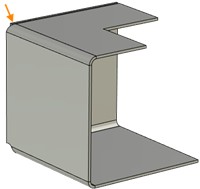
After the operation is executed, we obtain a solid body with two sheets with non-deformed corners crossing a rounded face. This is because the body folding sequence was given incorrectly.
This is exactly one of the cases when it is helpful to change edges folding sequence. It helps to avoid self-intersection of the bodies, at the same time you don’t have to re-set the edges manually.
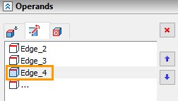
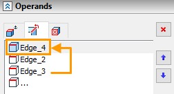
Operands tab shows edges selection sequence for the operation. Use arrows ![]() and
and ![]() to change folding sequence.
to change folding sequence.
|
|
Move the last of the selected edges two lines higher, selecting the required edge and pressing up arrow and repeat operation creation. Now the sheets adjoin each other smoothly and don’t intersect.