Identifying Failing Elements and the Reasons of Model Regeneration Errors


Identifying Failing Elements and the Reasons of Model Regeneration Errors |
  
|
Upon encountering errors during the model recalculation, the system outputs relevant signals. The user shall be able to correctly interpret those in order to proceed with a sound and quick fix to the source of errors and restore the model validity.
Diagnostics Window
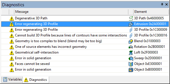
The “Diagnostics” tool window serves to output various system messages regarding errors in the model encountered during a recalculation, as well as warnings and information messages.
Messages are output in the diagnostics window line by line. Each line includes the message type symbol (![]()
![]()
![]() error-type, info-type, etc.), a brief description of the message cause and the name/ID of the model element. In addition, the name/identifier of the “problem” element of the model is specified in the message.
error-type, info-type, etc.), a brief description of the message cause and the name/ID of the model element. In addition, the name/identifier of the “problem” element of the model is specified in the message.

Below we review the most typical errors occurring in the course of model recalculation:
Message text |
Remarks |
|
A geometrical parameter specified in the operation's properties (for example, a blend radius) does not support a valid result under the current conditions. To correct the error, check the geometry near the location of the operation or modify the geometrical parameter value. |
|
One or more elements used as the base for the concerned operation failed the regeneration for some reason. The operation cannot be recalculated because of a missing source element. To correct the error, try to restore the source element or redefine the operation. |
|
The source data used for constructing the element (usually, a 3D profile or a 3D path) for some reason does not support a correct construction of the element. To correct this error, check the source 2D construction elements (for such issues as self-intersecting hatches, open contours etc.). |
Link to Nonexistent File |
The system couldn't find the required file neither by the specified path nor in the assembly folder. |
|
The system encountered additional errors when recalculating the element, which lead to an invalid result. |
|
The operation's input parameters do not support a valid result. Modify the source elements or the operation's geometrical parameters. |
|
A Boolean operand could be missing due to an error in its regeneration or due to parametric modifications of the model that caused the body to disappear. In this case, only one operand is left, and the Boolean operation no longer makes sense within the sequence of the model's operations. It could be the case, however, that such "blinking" elements are intentional instances within a family of parametric versions of the part. The Boolean operation provides an option among its parameters to allow a missing operand. |
|
This is a general message conveying the fact that errors were encountered when regenerating a model of a Part or a 3D fragment. You need to investigate the fragment's model to correct the error. Use the command “Open Fragment”, “Detail”. |
|
In most cases, the system warns the user by this message in advance about an attempt to create recursive relations (that is, the element's dependencies on itself). This message being displayed during model regeneration means the model already has recursive relations. To resume the normal function, make sure you find and break the recursion by redefining the elements with invalid relations. |
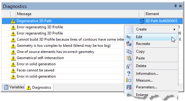
Upon error messages being displayed in the diagnostics, make sure to investigate and fix their causes. By selecting a message line in the diagnostics window you automatically select the respective element. You can call the context menu containing the commands for the selected element by ![]() , which includes the editing commands (see “Editing Techniques” below).
, which includes the editing commands (see “Editing Techniques” below).

Diagnostics may include messages about the regeneration errors which occurred during recalculation of 3D fragments. In this case, the context menu will provide the command “Show Fragment Structure”. Once this command is called, the system will show in what fragment the error occurred. Next, depending on the situation, you can use the command “Open Fragment” or “Detail” to investigate the fragment's model.
Since model elements are related with each other, a failure in one element may simultaneously cause a sequence of errors in other elements. In a case like that, you need to start fixing problems from the very first failing element. Therefore, if you see several messages, first pay your attention to the beginning of the list in the upper part of the diagnostics window.
Sometimes, it is not the element triggering a recalculation error that actually needs to be fixed, but rather one of its “parents”. For example, a 3D profile doesn't cause regeneration errors by itself, but its geometry may not support valid calculation of a further operation. In such a case, you need to look for the reason why the 3D profile changed. Maybe, that reason originates on the workplane page that contains the source construction for the profile. After that, the error in the child 3D element may disappear automatically.
“3D Model” Window
Working with the diagnostics may be enhanced by using the 3D model structure in the “3D Model” window for finding the desired element. The model elements within which errors are detected are marked by special signs:
●A red cross on an element ( ●A red arrow attached to the icon of a 3D element ( ●A blue cross on an element ( To reach the failing element, you need to expand the branches of the model tree and follow the tree structure, finding the so marked elements. |
|