Editing Hatches and Fills


Editing Hatches and Fills |
  
|
To modify hatches or fills, use the command "EH: Edit Hatch".
Keyboard |
Textual Menu |
Icon |
<EH> |
"Edit|Draw|Hatch" |
|
Select a hatch or a fill by clicking ![]() . One can also use element selection from list, if the element was named. Upon selecting a hatch or fill, the following actions can be performed:
. One can also use element selection from list, if the element was named. Upon selecting a hatch or fill, the following actions can be performed:
Modifying hatch or fill parameters
This is done via the option <P> that lets modifying hatch (fill) parameters (see parameter description above). One can change the hatch type, for example, from pattern to solid fill. This will fill the contour per the settings for new fill creation.
As in hatch creation, some of the parameters are accessible from the system toolbar upon hatch selection.
Deleting the whole hatch or fill
To do this, press the <Del> key (the icon ![]() in the automenu).
in the automenu).
In the case when a hatch is referenced by the 3D model, its direct deletion is impossible. The user will have to delete all dependent elements referencing the hatch, which may not be desirable. In such cases, it may be possible to edit the hatch contour. This opportunity is described below.
As in the case of any other model elements, multiple selection of hatches is supported for simultaneous deletion or modifying their parameters.
Adding a contour to a hatch or fill
This is done similar to hatch (fill) contour initial input. Suppose, given a hatch, we'd like to make a hole within. To do this, select the hatch and turn on the contour addition mode (the icon ![]() or <M> key). Then, using the option <C>, input the additional contour – a full circle, and press <End>. The result will be a hatch with a "cut" hole.
or <M> key). Then, using the option <C>, input the additional contour – a full circle, and press <End>. The result will be a hatch with a "cut" hole.
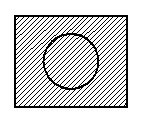
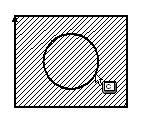
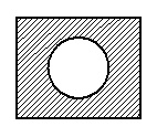
Redefining hatch contour
Select the hatch whose contour is to be redefined, and use the option
![]() <К> Redefine Hatch Contours
<К> Redefine Hatch Contours
To input a new hatch contour, using manual or automatic contour input mode. The edited hatch will assume the new shape upon confirming the input with the ![]() option.
option.
Defining the hatch start point
A start point can be defined for a hatch (either the regular or by pattern or for a fill with a circular color transition). The start point defines the location from which hatching begins.
The start node can be defined by the option:
![]() <O> Select Starting Node of Hatch
<O> Select Starting Node of Hatch
Upon calling the option, simply click the desired node with ![]() .
.
To reject the start node input, use the option:
![]() <T> Cancel selection of starting Node of Hatch
<T> Cancel selection of starting Node of Hatch
Displaying the contour point numbers of a hatch
To toggle the display of the contour point numbers of a hatch, use the option:
![]() <Q> Show/Hide contour point numbers
<Q> Show/Hide contour point numbers
With the option turned on, the points in the all hatch contours are enumerated based on their position in the contours and the contours direction. Points, belonging to the different contours, are enumerated independently. The point numbers are displayed next to the respective nodes. When several subsequent points of a contour coincide, their numbers are displayed next to each other, separated by commas.
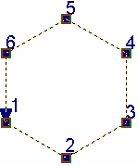
Editing a particular contour
Note: only manually defined hatch contours can be edited.
First, select the hatch that includes the desired contour. Then, turn on the contour editing option using the option:
![]() <М> Contour edit mode
<М> Contour edit mode
Now, select the desired contour. The selected contour can be deleted or edited. To delete it, press the <Del> key. When picking a contour, the segment of the contour nearest to the cursor gets automatically selected. Now, the necessary modifications can be done with the help of the automenu.
The following options become available upon selecting a contour segment:
|
<I> |
Switch to “Insert Point” mode |
|
<Q> |
Show/Hide contour point numbers |
|
<Del> |
Delete selected Contour |
|
<R> |
Change Contour direction |
|
<F> |
Move Contour starting point forward |
|
<B> |
Move Contour starting point backward |
|
<N> |
Select Node |
|
<L> |
Straighten Contour Segment |
|
<C> |
Select Circle |
|
<E> |
Select Ellipse |
|
<S> |
Select Spline |
|
<Tab> |
Change arc direction (available when editing an arc segment of a contour) |
|
<A> |
Link Arc or Circle to Node |
|
<K> |
Break Link with Node |
|
<Esc> |
Cancel selection |
Note: the options ![]() and
and ![]() only are available for editing the contours defined automatically with the option
only are available for editing the contours defined automatically with the option ![]() , constructed on top of 2D projections or as a copy of an existing hatch.
, constructed on top of 2D projections or as a copy of an existing hatch.
When editing a contour, the following actions are supported: node deletion, node addition and redefinition of the type of lines connecting the nodes. Besides, one can change the contour direction, move the start point back and forth, link arc segments of a contour to nodes.
Flipping contour direction to the opposite
The contour direction is an important hatch property when creating 3D elements. This parameter is inherited by the 3D profiles created based on hatches. For example, the 3D operation "Loft" matches profiles by the start points of the respective contours and requires matching of contour directions as well.
To change the direction of a 3D profile constructed based on a hatch, you need to change the hatch contour direction.
The contour direction is shown by the arrow displayed upon selecting the contour. This arrow also indicates the start point of the contour.
The following steps are to be done in order to change a hatch contour direction:
- Call the command "EH: Edit Hatch";
- Select a hatch for editing;
- Turn on the contour editing mode (the icon ![]() or <M> key);
or <M> key);
- Select the contour (point the graphic cursor at and click ![]() );
);
- Flip the contour direction (the icon ![]() or <R> key);
or <R> key);
- Confirm changes by the ![]() icon or <End> key.
icon or <End> key.
Moving around contour start
The contour start is the first node selected during the manual hatch contour input.
If the contour is defined automatically or without node selection (as by a full circle), the start point is defined automatically.
The start point placement and contour direction (see above) can only be changed for the contours defined manually.
To move the contour start point, do the following steps:
- Call the command "EH: Edit Hatch";
- Select a hatch for editing;
- Turn on the contour editing mode (the icon ![]() or <M> key);
or <M> key);
- Select the contour (point at it with the graphic cursor and click ![]() );
);
- Move the start point forward (the icon ![]() or <F> key) or backward (the icon
or <F> key) or backward (the icon ![]() or <B> key);
or <B> key);
- Confirm changes by the ![]() icon or the <End> key.
icon or the <End> key.
Editing a particular segment in contour
To edit a contour segment, do the following steps:
- while in contour editing mode, select the desired contour segment;
- select the construction element defining the new contour segment: line, circle, ellipse or spline (use the appropriate option for element selection). The end nodes of the contour segment must be snapped to the selected construction element;
- confirm changes by the ![]() or <End> key.
or <End> key.
Let's review an example illustrating a particular contour segment editing. The diagram shows the original hatch constructed along construction lines using the "Outline" option. Here, a straight-line segment is to be replaced by a spline. To do so, call the command "EH: Edit Hatch" and select the hatch.
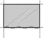
Then, turn on the contour editing mode using the option:
![]() <M> Contour edit mode
<M> Contour edit mode
Select the hatch contour. The following diagram shows the situation after the hatch selection. The contour is highlighted, and the nodes are marked by little boxes. Move the cursor over the desired segment of the contour and click the left mouse button. The selected contour segment also gets highlighted, and the nodes marked by larger boxes. This state is shown on the center diagram. Move the cursor over the spline constructed through the nodes of the contour being edited, and select it as a contour segment by typing <S>.
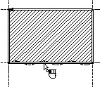
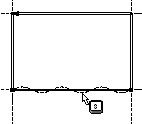
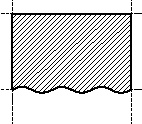
Similarly, one can replace a contour segment by an arc or ellipse, if the respective circle or ellipse is constructed based on the marked nodes. Simply use the appropriate option: <C> or <E>. If the new contour segment was not constructed based on the marked nodes yet passes through them then the contour segment editing should be done via the option "Switch to 'Insert Point' mode" (the icon ![]() or <I> key). This option functionality is described below.
or <I> key). This option functionality is described below.
The edited segment will then assume the desired shape. The system is still in the mode of modifying the selected contour segment. If the manipulations with this segment are over, complete the contour segment modification mode. To do so, press the ![]() icon in the automenu.
icon in the automenu.
The option <Space> is not available for editing the contour. Therefore, it is impossible to snap a contour line to a graphic line. If a contour segment is to be replaced by a graphic line while editing, as, for instance, a wave line, then you need to construct a spline based on the wave line. The intended hatch contour segment can then straightforwardly be replaced by the spline.
Linking arc contour segment to helper node
If the edited contour segment is an arc then the option for linking to a helper node ![]() becomes available in the automenu. This node will be defining the choice of an arc constructed on top of the circle to be used for the hatch contour. As the drawing gets modified, the hatch contour will pass by the arc nearest to the linking node.
becomes available in the automenu. This node will be defining the choice of an arc constructed on top of the circle to be used for the hatch contour. As the drawing gets modified, the hatch contour will pass by the arc nearest to the linking node.
Let's review an example where a construction line position is modified with respect to a reference line driven by a variable "K". Both circles here are linked to a node on the drawing in order to ensure correct position. The left diagram shows the hatch contour in the original configuration (K=1). Let's link the arc segment of the hatch contour on top of the outer circle to the marked node. To do this, do the following steps once in "EH: Edit Hatch" command:
- Call the hatch contour editing option ![]() ;
;
- Select the arc;
- Call the option ![]() ;
;
- Select the linking node.
The right diagram shows the modified drawing with the "К" equal to (-1). The contour segment on top of the upper circle was linked to the marked node and adjusted correctly. The contour segment on top of the second circle was not linked to the node, which resulted in an incorrect configuration.
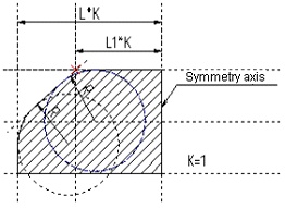
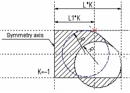
To clear or redefine the linking node, use the option ![]() .
.
Deleting a node on a contour
To delete a node on a contour, do the following steps:
- Call the command "EH: Edit Hatch";
- Select a hatch for editing;
- Turn on the contour editing mode (the icon ![]() or <M> key);
or <M> key);
- Select the contour segment the node is snapped to (point at with the graphic cursor and click ![]() );
);
- Select the node (point at with the graphic cursor and click ![]() );
);
- Delete the node (the icon ![]() or <Del> key);
or <Del> key);
- Confirm changes (the icon ![]() or the <End> key). The resulting new hatch contour passes through two adjacent nodes.
or the <End> key). The resulting new hatch contour passes through two adjacent nodes.
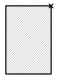
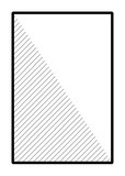
Modifying a contour node position
To modify a contour node position, do the following steps:
- Call the command "EH: Edit Hatch";
- Select a hatch for editing;
- Turn on the contour editing mode (the icon ![]() or <M> key);
or <M> key);
- Select the contour segment of the node (point at with the graphic cursor and click ![]() );
);
- Select the node (point at with the graphic cursor and click ![]() );
);
- Move the node to the desired position (the contour rubberbands after the cursor as the node is being dragged);
- Fix the node (click ![]() over an intersection point or type <N> key for an existing node);
over an intersection point or type <N> key for an existing node);
- Confirm changes (the icon ![]() or the <End> key). As a result of moving, the node point will be connected with the neighbor nodes by straight line segments belonging to the contour (regardless of the former adjacent segment entity types).
or the <End> key). As a result of moving, the node point will be connected with the neighbor nodes by straight line segments belonging to the contour (regardless of the former adjacent segment entity types).
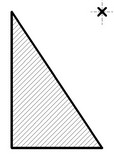
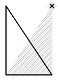
Creation of additional nodes on a contour
To create additional nodes on a contour, do the following steps:
- Call the command "EH: Edit Hatch";
- Select a hatch for editing;
- Turn on the contour editing mode(the icon ![]() or <M> key);
or <M> key);
- Select the contour segment to split by new node(s) (point at with the graphic cursor and click ![]() );
);
- Turn on the point insertion mode (the icon ![]() or the <I> key), and click on a contour segment. The segment becomes split in two, with the new node between them. The node and the segments rubberband with the cursor, the solid line segment connecting to the previous node and the dashed line one to the next. The order of the nodes after the insertion will be determined by the system automatically, depending on the hatch contour direction. Do not click on a segment near a vertex, as, instead of adding a node, this will start moving the existing node;
or the <I> key), and click on a contour segment. The segment becomes split in two, with the new node between them. The node and the segments rubberband with the cursor, the solid line segment connecting to the previous node and the dashed line one to the next. The order of the nodes after the insertion will be determined by the system automatically, depending on the hatch contour direction. Do not click on a segment near a vertex, as, instead of adding a node, this will start moving the existing node;
- Close the contour between the newly created node and the successive one.
Contour input is complete once the closing node is selected, or the icon ![]() or the <End> key is pressed.
or the <End> key is pressed.
The system returns to the mode "Contour selected for editing". One can do other modifications, and then confirm all changes.
- Confirm changes (the icon ![]() or the <End> key).
or the <End> key).
Let us illustrate the above with a specific example. Suppose, a hatch contour needs to be edited that was originally constructed along construction lines using the "Outline" option. The original and target configurations are shown on the diagrams.
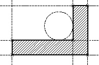
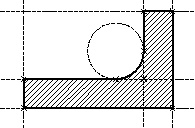
To get the result, begin with calling the command "EH: Edit Hatch". Next, select the hatch and turn on the contour editing mode. Select the hatch contour to be modified. Now, to get the result, perform manipulations shown on the following diagrams 1 – 8.
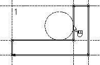
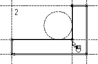
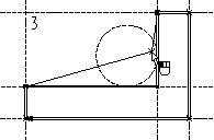
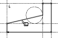
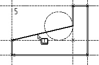
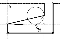
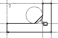
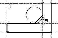
Upon selecting the closing node (see diagram 8) the contour automatically closes, and the point insertion mode exits. What is left is to press the ![]() icon or the <End> key, and the contour editing task is completed.
icon or the <End> key, and the contour editing task is completed.
One comment to the described procedure: as the contour segment to be modified is selected (see diagram 5), the system will define the previous and the next nodes in the sequence, depending on the hatch contour direction. These will be identified by the dashed and solid rubberbanded lines. In this particular example, the hatch contour direction is clock-wise.