Editing Roughness Symbol


Editing Roughness Symbol |
  
|
The command "ERO: Edit Roughness Symbol" allows changing the attachment, position and the parameter values of a roughness symbol (alternatively, use the option <F4> in the command "RO: Create Roughness Symbol"):
Keyboard |
Textual Menu |
Icon |
<ER> |
"Edit|Draw|Roughness Symbol" |
|
Upon calling the command, the following icons are available in the automenu:
![]() <*> Select All Elements
<*> Select All Elements
![]() <Esc> Exit command
<Esc> Exit command
A roughness symbol notation can be selected by pointing at with the mouse and clicking ![]() , or by multiple selections. As in the case of other drawing elements, multiple selections are done by the option
, or by multiple selections. As in the case of other drawing elements, multiple selections are done by the option ![]() . Using
. Using ![]() together with the depressed key <Shift> adds an element to the list of selected, while with the key <Ctrl> - excludes from the selected list.
together with the depressed key <Shift> adds an element to the list of selected, while with the key <Ctrl> - excludes from the selected list.
For multiple selections, you can use the options:
![]() <P> Set Roughness Symbol Parameters
<P> Set Roughness Symbol Parameters
![]() <Alt+P> Copy Properties from Existing Element
<Alt+P> Copy Properties from Existing Element
![]() <Del> Delete selected Element(s)
<Del> Delete selected Element(s)
![]() <Esc> Cancel selection
<Esc> Cancel selection
When selecting a single element, the properties window displays parameters of the selected element. The following icons become available in the automenu:
![]() <P> Set Roughness Symbol Parameters
<P> Set Roughness Symbol Parameters
![]() <Alt+P> Copy Properties from Existing Element
<Alt+P> Copy Properties from Existing Element
![]() <K> Break (kill) relations (available when the selected roughness is attached to a node, construction or graphic entity)
<K> Break (kill) relations (available when the selected roughness is attached to a node, construction or graphic entity)
![]() <H> Change leader / roughness position (available when selecting a roughness symbol with a leader)
<H> Change leader / roughness position (available when selecting a roughness symbol with a leader)
![]() <Z> Change leader line jog orientation (available only when selecting a roughness symbol with a leader)
<Z> Change leader line jog orientation (available only when selecting a roughness symbol with a leader)
![]() <T> Link to Node
<T> Link to Node
![]() <Space> Change Roughness Attach type
<Space> Change Roughness Attach type
![]() <N> Set relation with Node*
<N> Set relation with Node*
![]() <L> Set relation with Line*
<L> Set relation with Line*
![]() <C> Set relation with Circle*
<C> Set relation with Circle*
![]() <D> Set relation with Dimension
<D> Set relation with Dimension
![]() <E> Set relation with Ellipse*
<E> Set relation with Ellipse*
![]() <S> Set relation with Spline*
<S> Set relation with Spline*
![]() <I> Select Other Element
<I> Select Other Element
![]() <Del> Delete selected Element(s)
<Del> Delete selected Element(s)
![]() <Esc> Cancel selection
<Esc> Cancel selection
* The respective attachment element selection option is available if the selected roughness symbol was defined in the absolute coordinates, or if the attachment of this element was canceled by the option ![]() .
.
Once selected, the roughness symbol starts rubberbanding on the screen, following the pointer. The option ![]() allows selecting which point of the roughness notation to rubberband - the arrow tip or the leader jog. Clicking
allows selecting which point of the roughness notation to rubberband - the arrow tip or the leader jog. Clicking ![]() fixes the roughness symbol in the new position.
fixes the roughness symbol in the new position.
To change the attachment type, first you need to cancel the original attachment by using the option ![]() (<K>). After that, the options will be provided in the automenu for selecting new attachment elements: <N>, <L>, <C>, <S>, <D>. If the position of the selected roughness symbol was defined in the absolute coordinates, then you do not need to use the first option <K>.
(<K>). After that, the options will be provided in the automenu for selecting new attachment elements: <N>, <L>, <C>, <S>, <D>. If the position of the selected roughness symbol was defined in the absolute coordinates, then you do not need to use the first option <K>.
Node, that roughnesses on lines, dimensions and circles can assume two opposite positions.


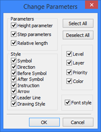
The option <P> allows modifying parameters of the several selected roughness symbols. Modifying parameters in the case of selecting a single element is similar to defining the roughness parameters. However, if you selected multiple roughnesses for editing, then you need to determine first, which parameters to modify, in the "Change parameters" dialog box. By default, all parameters of the selected elements are subject to editing. Upon selecting parameters for editing and pressing [OK], you will access the standard dialog box for defining roughness parameters. Option ![]() takes parameters of roughness symbol from existing roughness symbol. To delete a roughness symbol, select it, and then press the <Del> key.
takes parameters of roughness symbol from existing roughness symbol. To delete a roughness symbol, select it, and then press the <Del> key.
