Forming Feature


Forming Feature |
|
To create sheet forming elements a SMF: Forming Feature command is used:
Icon |
Ribbon |
|---|---|
|
Sheet Metal → Forming Feature |
Keyboard |
Textual Menu |
<SMF> |
Operation > Sheet Metal > Forming Feature |
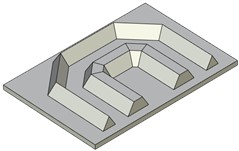
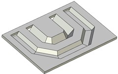
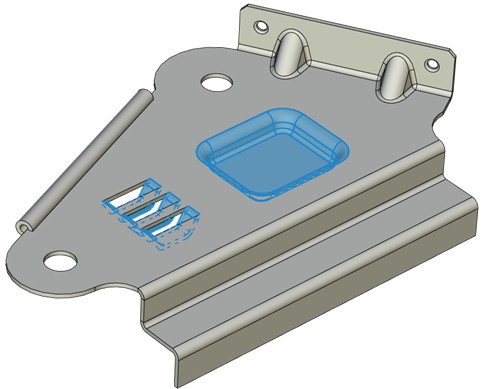
The operation enables users to create forming elements at sheet bodies. Forming elements from standard or user libraries can be used.
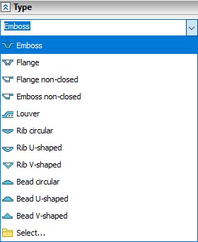
Pimple type can be chosen from a drop-down list or by an icon showing the pimple type. If a pimple type whose icon is absent is chosen from the list, the last right icon will be replaced with the icon of the last chosen type.
Pimple types and their icons are given below.
|
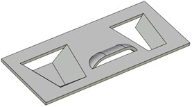
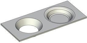
Emboss |
|
Flange |
|
Flange non-closed |
|
Emboss non-closed |
|
Louver |
Choosing from the standard list:
|
|
Collar, V-shape, U-shape |
Groove, U-shape, V-shape |
|
|
Cradle, Airway, Round fold |
Flanging, Stamping |
There is a Select point in the drop-down list of choosing pimple type. It enables you to choose elements from user libraries. The content of the list is connected with the type chosen in the Standard field. The list changes if the standard is changed.
The following option is used for choosing the forming libraries:
|
<B> |
Library Configuration |
More information about forming features creation can be found in “Create custom elements for sheet metal and holes libraries” chapter.
A special library of typical stamping elements Sheet Metal Features supplied with the system is used for creating elements. If necessary, the library can be completed with the elements of your own.
If inches are set as the units of length in ST: Document Parameters command in 3D tab, then Sheet Metal Features Inch library will be used when creating pimple.
Command parameters
Type. Enables users to choose pimple type from the list or by icon.
Standard. Enables users to choose standard from the list. It is metric by default.
The rest of the parameters depend on the pimple type chosen.
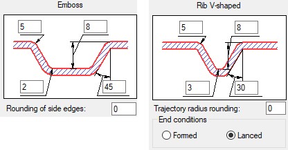
Parameter dialog for every element contains a sketch of the element being created with entry fields for all the geometric dimensions.
Command automenu options are:
|
<Ctrl+Enter> |
Finish input |
|
<P> |
Set entity Parameters |
|
<X> |
Exit command |
|
<F5> |
Preview Operation Result |
|
<B> |
Library Configuration |
|
<R> |
Select 3D profile |
|
<F> |
Draw Profile |
Finish input. To build geometry according to the given parameters. In case the parameters are insufficient, the option in not available.
Set entity Parameters. Call a standard 3-D design command parameters dialog.
Exit command. Shuts down the command cancelling the given parameters.
Preview Operation Result. The option enables/disables a standard option for reviewing 3-D design commands.
Library Configuration. The option calls library selection dialog.
Select 3D profile. The option chooses a 3D profile which will be the base for operation creation. The option is active by default.
Draw Profile. The option enables you to build a profile in the transparent mode. You should choose a workpiece face and the system automatically switches over to drawing work plane mode. Then you build an outline within the face. The created profile will be selected automatically on exiting from the drawing on the work plane mode.
Creating a pimple element
To create a pimple element you should follow these typical steps:
●Select a 3D profile which will be the base for operation creation. Profile choosing mode activates automatically at entering the command.
●Choose the pimple element needed from the ones given in the library from the command parameters window (a parameter dialog for the element chosen will appear in the bottom part of the window).
●Set the appropriate values of the parameters.
●Finish entering.