Basic Fundamentals and Concepts of Working with Fragments


Basic Fundamentals and Concepts of Working with Fragments |
  
|
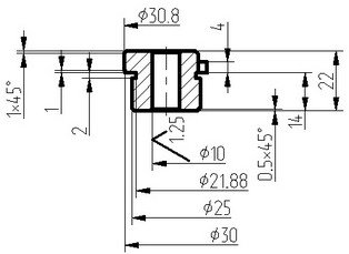
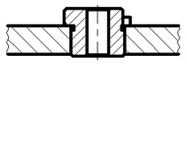
Any drawing can be inserted in other drawings in T-FLEX system. For example, you can insert the drawing of the title block template into a part drawing, or, say, a drawing of a bolt into an assembly.
A T-FLEX CAD drawing is called fragment when inserted into another document. The drawing obtained by using fragments will be referred to as assembly drawing. The assembly drawing keeps only a reference to the original fragment file. Modifications in the fragment file propagate on the respective component in the assembly drawing.
Creation of drawings using fragments brings significant benefits in various cases. Firstly, this simplifies the process of creating complicated drawings, since you can create portions of such drawing first, and then join those. The design workflow of separate fragments can be completely independent, or, alternatively, be conducted in the assembly context, using the associative relations between the fragments and the assembly. Separating the assembly drawing into fragments corresponding to separate parts makes the assembly drawing fully represent the actual assembled mechanism. This approach also provides maximum automation to creating bills of materials of the assembly drawing, and delivers the complete set of detail drawings. Secondly, the use of assembly drawing supports reverse propagation of parametric modifications to any of the assembly parameters from the assembly to its contributing parts. This feature instantly yields a full set of part drawings satisfying those modified parameters. Thirdly, fragments can serve for representing frequently used drawing elements. Standard library elements can also be handy as fragments. For example, the title block template drawing can be added to a part drawing. You could also create special detailing elements to add to drawings.
Effective use of fragments in T-FLEX assembly drawings relies on the following fragment characteristics:
As any T-FLEX CAD elements, fragments can be attached to various elements of the assembly drawing, including other fragments. This allows coordinating fragment position modifications with other drawing elements relocations.

Since fragments are parametric drawings, they dimensions upon assembling are calculated according to the desired parameters of the assembly drawing. Note that the same fragment file can be used in the assembly document multiple times with different parameter values. This feature is especially beneficial when using libraries of standard elements.

Once assembled, fragments often overlap each other and the image of the assembly itself. T-FLEX CAD allows setting up automatic hidden line removal upon fragment overlapping.

You can do selective insertion of only necessary elements from the fragment drawing into the assembly drawing. This capability allows using fully furnished part drawings in assemblies. Fragments can be variable, meaning that one or another fragment would be inserted in the assembly drawing, depending on certain conditions. This capability allows creating assembly drawings and modeling products in various configurations, when different parts are put in the same assembly, depending on the configuration.


Assembly drawings do not directly incorporate all fragment data. They only keep the necessary images and references to fragment drawings. This helps achieving most compact representation of the drawings in the memory and on the hard disk. Besides, if the same drawing file is inserted in different assemblies, then its modifications will propagate on all documents that use it.