Common Parameters of Sheet Metal Commands > Bend Relief |
  
|
Common Parameters of Sheet Metal Commands > Bend Relief |
|
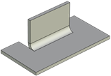
A group of parameters by which special grooves can be defined to reduce stresses in the metal, concentrated at the bending angles.
Bending operations allow you to create a Bend Relief automatically when performing certain operations. Reliefs are divided into Corner and Isolating. Isolating relief allows you to remove stress in the bendable flange. Corner relief allows you to remove stress at the joint of the flanges and walls. Corner reliefs can be specified with a separate Corner command.

1 - Corner relief; 2 - Isolating relief
The Isolating type has two variations, selected from the list: Round and Linear. The Extend Relief option is available for each of the variants.
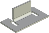
No reliefs
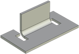
Isolating relief
|
|
|
Round reliefs |
Square reliefs |
Square reliefs through |
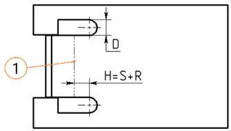
Depth and Width parameters are available to determine the geometry of the isolating reliefs. For a square relief, those define the width of the groove and the length of the groove part ahead of the bend line, respectively. In the case of the round relief, the length of the head portion of the slot is increased by the radius of the end fillet. The fillet radius is equal to half the groove width.
The rear part of a groove of any type can be arranged in one of two ways:
•to the depth equal to bend radius plus workpiece thickness;
•extended up to the borders of the workpiece (if the Extend Relief option is enabled) or to the end of the workpiece, if gluing a flange inside the workpiece with material removal by the flange length.
|
|
|
1 - bend line, S - workpiece thickness, R - bend radius, D - width, H - depth |
||
Linear Reliefs (Non-Through) |
Round Reliefs (Non-Through) |
|
|
|
|
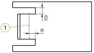
1 - bend line, S - workpiece thickness, R - bend radius, D - width, H - depth |
||
Square Reliefs (through to edge) |
Round Reliefs (through to edge) |
|
Following Corner relief types are available:
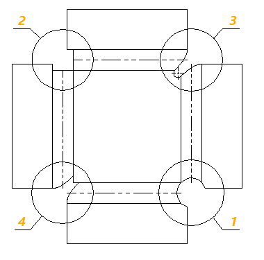
1 - Round
2 - Linear
3 - Welding
4 - No
Shape and dimensions of a corner relief are defined by its type and either by the value of the Extension parameter, or by the value of the Gap parameter and type of Overlap.
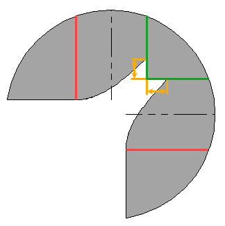
Round
A circular cut-out is made in unfolded part. The center of the circle is located at the intersection of bends' axes. Basic diameter of the circle is defined as the distance between its center and the intersection of bends' start lines. The Extension value is added to the radius. The Gap doesn't affect the geometry of the corner relief.


Green - bends' start lines
Magenta - bends' axes
Red - bends' end lines
Blue - minimal cut-out radius
Yellow - cut-out with extension
Orange - extension value
Linear
When the Extension is equal to zero, the cut-out in unfolded part is made by bends' start and end lines. When the Extension is not equal to zero, the cut-out in unfolded part is made by offsets from bends' start and end lines, where the offset values are defined by the extension. The Gap doesn't affect the geometry of the corner relief.


Green - bends' start lines
Red - bends' end lines
Yellow - cut-out with extension
Orange - extension value
Welding
Points are placed on bends' start lines at the Gap distance from their intersection point. If the Overlap is not applied, then the points are placed by both sides of the intersection, otherwise the first point is placed by by a one side, while the second point remains at the intersection. These points limit the cut-out of the deformed area. Across the deformed area, the cut-out is formed in such way, so that the specified Gap between adjacent flanges is ensured upon folding. Additionally, if the Overlap is not applied, then the points are connected by a fillet, which cuts off the angle of the initial workpiece. If the initial workpiece has a right angle at the relief zone, then the fillet has a constant radius, which is equal to Gap. In case of internal and external angles, the filled has a complex shape with variable curvature. Thus an optimal welding joint is formed in the bend area. Extension is not applicable to this type of corner relief.


Green - bends' start lines
Red - bends' end lines
Orange - gap value
No
Points are placed on bends' start lines at the Gap distance from their intersection point. If the Overlap is not applied, then the points are placed by both sides of the intersection, otherwise the first point is placed by by a one side, while the second point remains at the intersection. These points limit the cut-out of the deformed area. Across the deformed area, the cut-out is formed in such way, so that the specified Gap between adjacent flanges is ensured upon folding. The angle of the initial workpiece is not cut. Extension is not applicable to this type of corner relief.

Green - bends' start lines
Red - bends' end lines
Orange - gap value
See Also: