3D Weld Geometry Types: By Path |
  
|
When creating a weld by one path, the body of the weld is created by translation of the weld’s profile along the arbitrary guide. The guide of the weld can be closed.
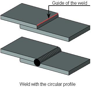
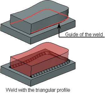
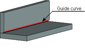
As a guide, the user can select edges, 3D paths, 3D profiles, etc. It is also possible to define the guide by a group of 3D elements (edges, paths, etc.) on condition that all selected elements form a continuous sequence.
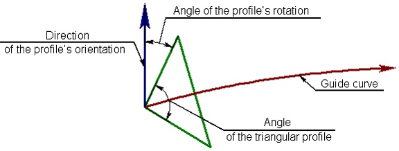
The shape of the profile is selected from two options offered by the system: circle or isosceles triangle. For the circular profile, the user defines the radius, for the triangular profile – the size of the leg and the size of the angle between the legs.
For specifying precise orientation of the triangular profile, the user has to define direction of the profile’s orientation and the angle of the profile’s rotation with respect to this direction. When creating the weld, the vertex of the triangle is superposed with a point on the guide, and one of the sides of the triangle is superposed with the given direction vector, and after that the profile is rotated through a required angle.
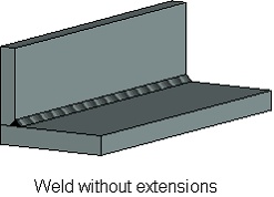
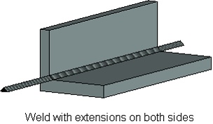
The length of the created weld is equal to the length of the guide. In cases where it is desirable to create the weld longer than the guide, the user can specify the magnitude of extensions at the ends of the guide. The body of the weld will be elongated along the tangent to the guide at its end points by a specified extension length.
