Main Concepts of Adaptive 3D Fragment |
  
|
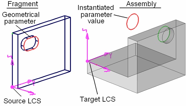
To use a 3D fragment as an adaptive model element, define in advance the set of geometrical parameters that can have relations with objects of an assembly model. Just like a set of external variables, a set of geometrical parameters is defined in the document of the given 3D fragment. The system allows defining geometrical parameters and their values actually at the time of inserting or editing a 3D fragment; however, the created relations will be used in this case only in the current assembly model. In such a case, this information will not be saved in the 3D fragment's document. When inserting an adaptive 3D fragment, the user specifies the values of geometrical parameters. The type of the instantiating object must be the same as the type of the object which is the parameter of the 3D fragment. For example, the instantiating value for a 3D profile can be defined only by a 3D profile.
The use of geometrical parameters for a 3D fragment can be combined with use of external variables and attachment coordinate systems. However, while doing so, keep in mind the specifics of instantiating a parameter object, as the substitution affects both the geometry of the adaptive parameter and its position in the assembly. As we know, the position of a 3D fragment in an assembly is defined by the source and target coordinate systems. Those coordinate systems can be specified by LCS or defaulted to the global coordinate systems of a 3D fragment and an assembly models.

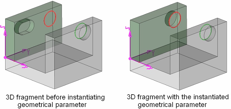
When instantiating the geometrical parameter, the system runs a "reverse" transformation by carrying the object from the assembly to the 3D fragment model, from the target LCS of the assembly towards the source LCS of the 3D fragment.

Upon instantiating the values, an adaptive 3D fragment is regenerated and inserted into the assembly model. The user needs to insure correct orientation of the parameter object instances to have them positioned according to the design intent upon embedding in the 3D fragment model.
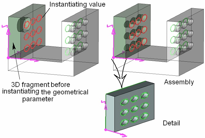
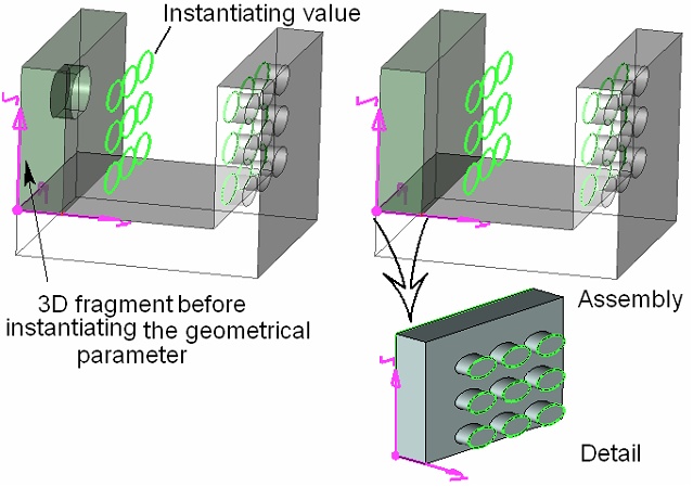
On the diagrams below, a 3D profile instance substitutes the original profile defining a hole in a wall of a 3D fragment. According to the intent, the new profile instance will serve for creating an array of holes in a wall of a 3D fragment. Among the two possibilities, in the first case the profile instance will be suitable for creating holes upon embedding in the 3D fragment model, while not so in the second case.


Let's review in details what happens with the 3D fragment model in the second case. Since a different instance of the 3D profile is used in this case, oriented differently with respect to the target LCS, then the result differs in the final position of the profile in the 3D fragment model. The detail view clearly shows that protruding the array of profiles in the second case does not lead to hole creation (to demonstrate that, the second operand of the Boolean subtraction was left in the scene); therefore, the 3D fragment is inserted in the assembly without holes in its wall.
If, upon inserting an adaptive 3D fragment, it is necessary to use the source coordinate system, then make sure that it is created based on 3D fragment Adaptive Elements (3D nodes, edges, vertices) that are independent of the external geometrical parameters. In other words, the parents of the source coordinate system shall not change upon instantiating adaptive elements.