Loft |
  
|
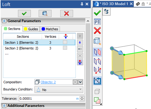
A lot of work has been done to update the Loft operation. Operation dialog has been completely updated.New17
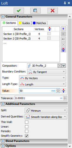
Working with the operation has become more clear thanks to a global redesign of the interface.
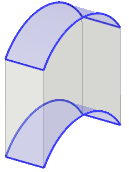
Added the ability to select non-planar sections.
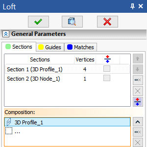
Now, in order to select a point or planar/non-planar section, you do not need to use additional commands in the automenu, because selection of both types of sections is carried out in the Composition field.
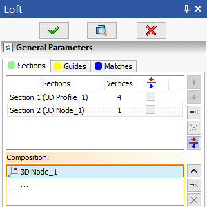
Now for each section, you can now set 4 boundary conditions – By Normal, By Tangent, By Geometry, By Vectors.
The Normal (outside) and Normal (to profiles) options have been moved to a separate boundary condition By Normal.
![]()
In all four types of boundary conditions, the option to reverse the direction of the vector or normal is available.
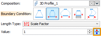
By Tangent option is now also included in the general list of boundary conditions.
![]()
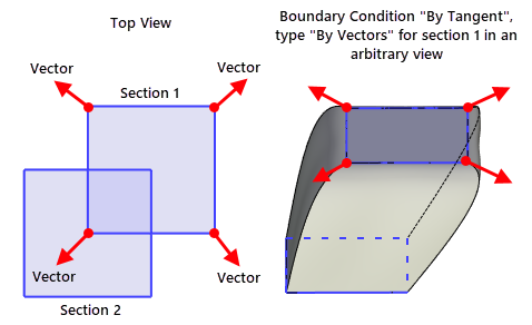
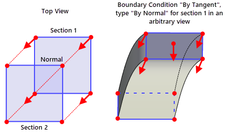
For this boundary condition, two types are available – By Vectors and By Normal.
The type By Vectors allows you to create a surface along planar and non-planar sections, taking into account vectors directed along the tangent. This is the "classic" type of the By Tangent boundary condition.
The type By Normal allows you to create a surface only by planar sections, taking into account the normal. A prerequisite for the creation of a surface is the presence of a normal at the section. The direction depends on the position of the next section.
To create a solid along the faces of other bodies, use the By Geometry boundary condition, which allows you to select a face or a set of faces.
![]()
For this type of boundary condition, you can set the curvature G1 or G2.
The window for specifying the vectors of boundary conditions has been moved to a separate boundary condition By Vectors.
![]()
Depending on the type of section, the user will be offered a certain set of parameters. If a point is selected as a section, then the user can specify the type of condition By Normal or By Tangent.
Condition type By Normal provides smooth ending for the created surface, limiting it to a tangent plane with a specified normal at the section-3D point.
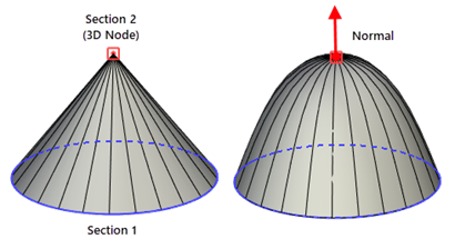
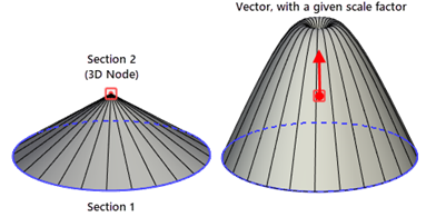
Condition type By Tangent Produces a more general ending which may or may not be smooth, constraining the surface by limiting it with a vector of derivatives in a section-point.
If a planar/non-planar section is selected as a section, then you can specify a set of vectors and select a first point for each. As the first point of a vector, you can select a point belonging to a section or an edge of this section and move along it using the manipulator or in the operation parameters window. In this case, you can select the type of coordinates By Offset or Parametric, and also specify the origin point Start, Middle or End similar to creating a 3D node on a curve.
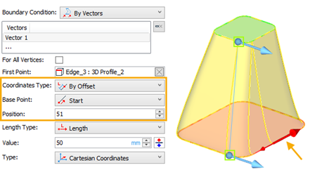
As before, for the boundary condition By Vectors, you can select the type of assignment - Spherical or Cartesian coordinates, By Two Points and By Direction of element.
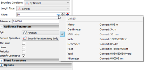
For all boundary conditions, as before, you can select the type of length - Length or Scale Factor and set the Value for which a choice of systems of units is now available.
The Guides and Matches tabs have also been reworked. For a guide, you can specify the boundary conditions By Geometry and By Vectors, similar to the boundary conditions for sections, and for matching points, you can specify the boundary condition By Vectors.
When the By Vectors boundary condition is selected, the For All Vertices option is available for planar/non-planar sections and guides, which allows you to select one vector for all section vertices, except for the vertices of intersection with the guides and except for the matching points that have boundary conditions.
In the new version of T-FLEX CAD, an emphasis is placed on maintaining the number of vertices for sections. For this, the number of section vertices is displayed in the section selection tab.
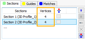
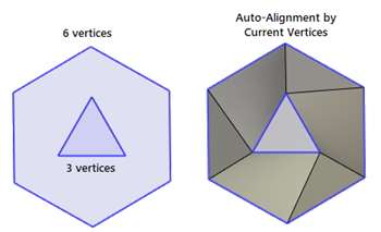
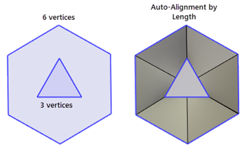
If the number of vertices is different, then for the correspondence points, you can set auto-alignment By Current Vertices or By Length.
The By Current Vertices option allows you to automatically align the match points to the vertices of the sections.
![]()
The By Length option allows you to automatically align the match points of the sections so that spacing between adjacent edges has the same ratio to total length.
![]()
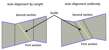
The Uniformly option allows to automatically align match points if at least one guide or one additional match is selected. If there is no guide and no matching, then the mode will work in the same way as the By Length mode.
![]()
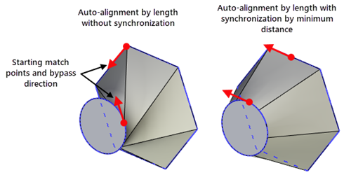
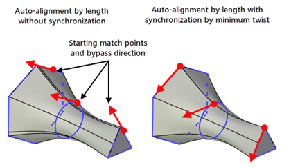
Added the Synchronize option, which allows you to automatically set the position of the starting points, ensuring the minimum distance between sections or minimum twist. This can be useful when circles or ellipses with only one starting point are used as sections.
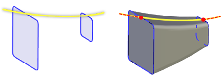
The option 3D Path has been changed to the Trajectory option. The selection of the trajectory allows the use of wire geometry, which will determine the shape of the result along all vertices of the sections.
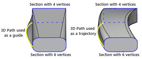
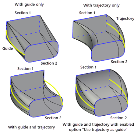
If nessesary, you can add both guides and trajectories at the same time. If a trajectory is selected and at least one guide is selected, the Use trajectory as guide option will become active.
Added the ability to trim guides and trajectories if they are longer than the section boundaries. The new option Trim - By End Sections will only use the part of the guide or trajectory that is located between the first and last sections.
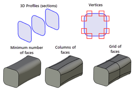
Keep initial splitting option, which displays the number of faces, has been replaced with the Split option, which contains three types of face splitting - Minimum, Columns of faces and Grid of faces. The first type allows you to create a body with a minimum number of faces. Columns are produced by dividing the body along the sections direction at each profile vertex, and a grid of faces is produced by dividing the body into columns and then dividing along the body according to the position of the sections.
For sections, special manipulators are added in the original vertices. Hovering over them invokes a tip with additional information:
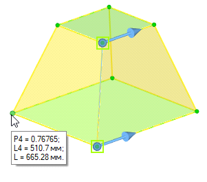
L - overall length of the section
L4 - length from the starting point to the current point, where 4 - the number of the current point
P4 - L4/L coefficient
The new ![]() Automatic Contour Search option was added to the automenu. If it's enabled (by default), the system automatically decides whether selected element should be included into one of existing sections/guides or a new section/guide should be added.
Automatic Contour Search option was added to the automenu. If it's enabled (by default), the system automatically decides whether selected element should be included into one of existing sections/guides or a new section/guide should be added.
