Derived Object |
  
|
The derived object (derived from object) allows you to transfer the geometry directly from a fragment at any level to the assembly file. The basic elements of the model (3D nodes, coordinate systems, workplanes, 3D profiles, 3D paths, bodies of various types), and geometric elements (edges, faces, vertexes) can become derived elements.
The derived element transfers the geometry from bottom to top. Therefore, all the principles of working with assemblies on the "Bottom-up" principle are valid for the derived element.
If we change the geometry in the fragment, including the geometry referenced by the assembly, and then save the fragment, the geometry of the derived element will be updated when the assembly is updated.
In General, an analogy can be drawn between a reference element and a derived one. A reference element provides a "Top-down" relationship (and a link between fragments), a derived element provides a "Bottom-up" relationship. But since the principles of updating the reference elements and derived elements are still different, you should not confuse them.
Derived object is similar to external element (External) by the principle of operation. You need to transfer sequentially on all levels from subassembly to subassembly only the external element, and the derived element can be transferred to assembly at once.
In an assembly, the derived element will be an element whose constructions tree is not available.
Derived Element Creation
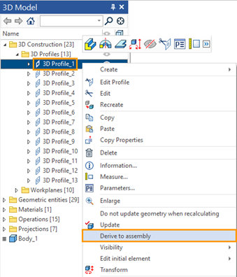
The command for deriving an element is available in the context menu of any element (listed above). To derive an element from a fragment to an assembly (or subassembly), you should first open the assembly (or subassembly) file. There are two ways to select the desired fragment element to derive it into the required assembly.
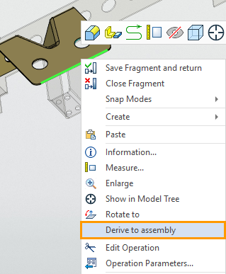
•Open a fragment in the context of an assembly, then open the context menu of the element by selecting it in the 3D scene or in the 3D Model window and specifying Derive to assembly.


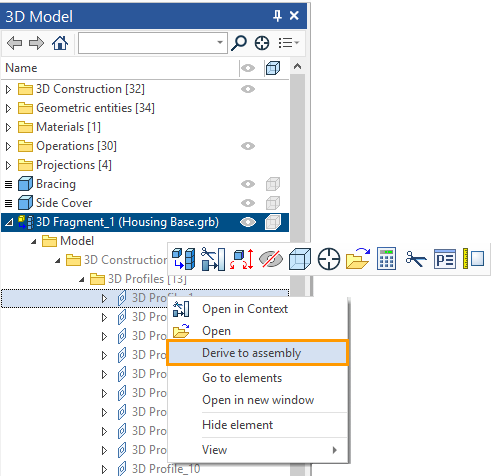
•In the 3D model window of the assembly file, expand the fragment constructions, find the required element and use its context menu to call the Derive to assembly command.

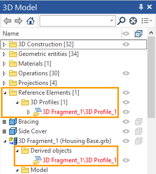
In the assembly file, we can see the derived elements. For an assembly, it will be a reference element, so the elements derived from the fragment, in the assembly file, are in the Reference elements folder. For a fragment, these are derived elements. In the 3D Model window of the assembly file, you can find a list of the derived elements in the corresponding folder of the fragment from which you derived the elements.

Automatic Creation of Derived Element
Automatic creation of derived elements is possible when we use the command Detail > Create and create a fragment (both adaptive and non-adaptive).
If there are parent elements of other bodies among the child elements of a body (which you want to keep in a separate fragment) then such elements cannot simply be taken from the assembly. In this case, the Derived Object is created. Derived Object will depend on the fragment and will define the geometry of the dependent bodies in the assembly.
For example, on a face of a body (which we want to save as a fragment), a profile is created, which is the parent of another body. This profile will be saved with the body to a fragment file. To ensure that the body dependent on the profile does not lose the parent element, a derived element will be created. The derived element will return the profile that is saved in the fragment file, to the assembly.