Flange |
  
|
Flange |
|
To create a flange on sheet parts Flange operation is used:
Icon |
Ribbon |
|---|---|
|
Sheet Metal (3D) > Operations > Flange |
Keyboard |
Textual Menu |
<SMA> |
Operation > Sheet Metal > Flange |
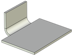
The flange thickness coincides with the part thickness and the width is determined by the base line (taking offsets into account). The flange displacement can be either outside or inside. You can set reliefs at the flange corners in the command and set treatment parameters of the intercepting flanges.
Command parameters
The command parameters are common for the sheet metal commands and are described in the corresponding subsection above.
The command menu options:
|
<Ctrl>+<Enter> |
Finish input |
|
<P> |
Set entity Parameters |
|
<X> |
Exit command |
|
<F5> |
Preview Operation Result |
|
<L> |
Select Line |
|
<M> |
Add Edges |
|
<E> |
Select first Vertex or 3D Node |
|
<S> |
Select second Vertex or 3D Node |
|
<R> |
Select Profile |
|
<W> |
Draw Profile |
|
<A> |
Cancel Selection |
Finish input. To build geometry according to the given parameters. In case the parameters are insufficient, the option in not available.
Set entity Parameters. Call a standard 3-D design command parameters dialog.
Exit command. Shuts down the command cancelling the given parameters.
Preview Operation Result. The option enables/disables a standard option for reviewing 3-D design commands.
Select Line. The option to select a line determining the base bending line.
Add Edges. The option to select an edge determining the base bending line. The option as active at entering the command on default.
Select first Vertex or 3D Node. The option to select the first point determining the base bending line.
Select second Vertex or 3D Node. The option to select the second point determining the base bending line.
Select Profile. The option enables you to build a flange whose shape is determined by the profile. This option is not to be mixed up with Contour Flange command where the profile sets the flange cross-section. In this case the profile sets the flange shape in the plane. The profile is to be closed.
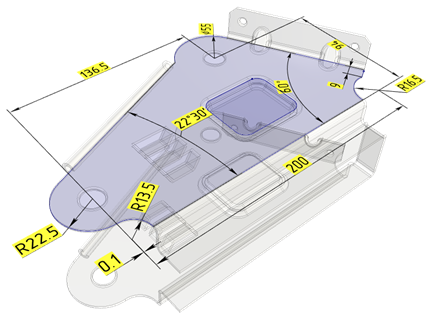
Flange by user 3D profile
Draw Profile. The option enables you to switch over to drawing work plane mode to create a profile. The system automatically activates drawing on the work plane which coincides with the face where the rib for building the flange was selected. In this case the created profile will be selected automatically on exiting from the drawing on the work plane mode and you don’t have to set it with Select Profile option. The profile is to be closed.
Cancel Selection. Cancel all elements selected and clear the operand window.
Flange creation
A typical procedure for creating a flange.
•Select an edge defining the bend baseline.
•Select a length reference.
•Set the position.
•Set the angle.
•Set the parameters of defining the flange shape or select a profile.
•Set the bend relief and offset parameters if necessary.
•Set the corner relief parameters if the flange has intersections with the workpiece.
•Set the overlapping variant if adjacent edges are selected.
•If the specified parameters allow creation of a valid flange, finish the input. Otherwise, change the parameters.
When moving the flange or building the flange by the base line which is not at the marginal edge of the workpiece, there are some peculiarities of setting command parameters.
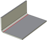
If offset is positive, an additional flat part is added at the base of the flange. The length of the flat part is defined by the Offset parameter. At negative offset the bending line is moved inwards the workpiece). See subsection Common Parameters of Sheet Metal Commands for details on the Offset parameter and the Position parameter associated with it.
|
|
|
|
Workpiece |
Flange without bending line offset |
Flange with bending line offset outwards |
Flange with bending line offset inwards |
In most cases the flange is attached at one of the side edges (it is realized by selecting the correspondent workpiece edge as a base line at zero offset relative to it). However, a flange can be attached inside the workpiece as well, e.g. when the negative offset in relation to the side edge, or when a baseline is selected inside the workpiece contour. In such cases, the workpiece material replaced by the attached flange is removed. The removed part width is defined by perpendiculars to the baseline running from its ends (taking flange cutting into account), similarly to bending. There are two variants of removing: either all the material to the end of the workpiece is removed, or the material at the attached flange's length is removed only.
|
|
|
|
Workpiece |
Flange |
Material removal to the end of the workpiece |
Material removal at the lug length |