Main Concepts of Transition Surface |
  
|
Main Concepts of Transition Surface |
|
![]() Conic – Discriminant. Builds a conic section surface with a smooth rounding shape between two curves lying on the given surfaces. The generating profile can be a parabola, an ellipse or a hyperbola. Discriminant parameter determines the degree of flatness for the surface obtained. It varies from 0 to 1 (not included). If Discriminant is less than 0.5, the generating profiles are hyperbola, if it is more than 0.5 – they are parabolas. If it is equal to 0.5, the generating profile is an ellipse arc. Therefore, the more the Discriminant, the less is the flatness of the surface created.
Conic – Discriminant. Builds a conic section surface with a smooth rounding shape between two curves lying on the given surfaces. The generating profile can be a parabola, an ellipse or a hyperbola. Discriminant parameter determines the degree of flatness for the surface obtained. It varies from 0 to 1 (not included). If Discriminant is less than 0.5, the generating profiles are hyperbola, if it is more than 0.5 – they are parabolas. If it is equal to 0.5, the generating profile is an ellipse arc. Therefore, the more the Discriminant, the less is the flatness of the surface created.
![]() Conic – Path. Builds a conic section surface with a smooth rounding shape between two curves lying on the given surfaces. The generating profile can be a parabola, an ellipse arc or a hyperbola. The rounding shape of the surface is determined by the intermediate path every generating profile has to pass. The position of every path point is limited with the triangle area as shown in the picture.
Conic – Path. Builds a conic section surface with a smooth rounding shape between two curves lying on the given surfaces. The generating profile can be a parabola, an ellipse arc or a hyperbola. The rounding shape of the surface is determined by the intermediate path every generating profile has to pass. The position of every path point is limited with the triangle area as shown in the picture.
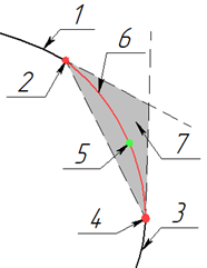
1 – first face; 2 –first guide point; 3 – second face; 4 –second guide point; 5 – point in the middle path; 6 – the surface obtained (surface generating profile); 7 – available region for the point in the middle path.
![]() Conic – Tangent. Builds a conic section surface with a smooth rounding shape between two curves lying on the given surfaces. The generating profile can be a parabola, an ellipse or a hyperbola. The surface rounding shape is determined by a reference surface set with two reference curves. The reference surface is invisible for the user if the reference curves selected don’t belong to the surface already built. The surface to be built must be tangent to the reference surface. At the same time the reference surface must allow every generating profile to be tangent to it. Otherwise the surface created will intersect the reference one without fulfilling the tangent condition.
Conic – Tangent. Builds a conic section surface with a smooth rounding shape between two curves lying on the given surfaces. The generating profile can be a parabola, an ellipse or a hyperbola. The surface rounding shape is determined by a reference surface set with two reference curves. The reference surface is invisible for the user if the reference curves selected don’t belong to the surface already built. The surface to be built must be tangent to the reference surface. At the same time the reference surface must allow every generating profile to be tangent to it. Otherwise the surface created will intersect the reference one without fulfilling the tangent condition.


1 – first face; 2 –first guide point; 3 – second face; 4 –second guide point; 5 – reference surface; 6 – first reference curve point; 7 – second reference curve point; 8 – surface obtained (surface generating profile).
![]() Conic - 4 Points. It creates a conic section surface that smoothly touches a given surface along the specified guide curve (First Guide), while the shape of the surface is determined by three other guide curves.
Conic - 4 Points. It creates a conic section surface that smoothly touches a given surface along the specified guide curve (First Guide), while the shape of the surface is determined by three other guide curves.
![]() Circle – Tangent to Surface. Builds a surface tangent to the selected surface. The surface generating profile is a circle arc with a given angle relative to the point of contact, the center of the arc lying at the curve set. The arc angle can be constant along all the surface length or it can vary which is set by a diagram.
Circle – Tangent to Surface. Builds a surface tangent to the selected surface. The surface generating profile is a circle arc with a given angle relative to the point of contact, the center of the arc lying at the curve set. The arc angle can be constant along all the surface length or it can vary which is set by a diagram.
![]() Circle – Radius. Builds a looped surface whose generating profiles are circles of a given radius. The radius can be constant or variable. The centers of the circles are determined by the selected curve.
Circle – Radius. Builds a looped surface whose generating profiles are circles of a given radius. The radius can be constant or variable. The centers of the circles are determined by the selected curve.
![]() Circle – Radius and Angle. Builds a surface which passes through a curve and is tangent to the surface the curve belongs to. The surface cross section is of circle arc shape with a set radius and angle. The radius and angle can be constant along all the surface length or it can vary which is set by a diagram.
Circle – Radius and Angle. Builds a surface which passes through a curve and is tangent to the surface the curve belongs to. The surface cross section is of circle arc shape with a set radius and angle. The radius and angle can be constant along all the surface length or it can vary which is set by a diagram.
![]() Circle – Three Points. Builds a surface which passes through three given curves. The surface cross section is of circle arc shape which is built by three points belonging to each of the three set curves. The curves can converge at one point.
Circle – Three Points. Builds a surface which passes through three given curves. The surface cross section is of circle arc shape which is built by three points belonging to each of the three set curves. The curves can converge at one point.
![]() Line – Angle. Builds a surface whose generating profiles are segments. Every segment is at a set angle to the selected surface. One end point of the segment lies at the surface, the other is at the directing line set by the user. The angle can be either constant or variable. At a zero angle the surface is built by the tangent line. The surface is limited by the initial directrix at one side and by the contact with the plane at the other.
Line – Angle. Builds a surface whose generating profiles are segments. Every segment is at a set angle to the selected surface. One end point of the segment lies at the surface, the other is at the directing line set by the user. The angle can be either constant or variable. At a zero angle the surface is built by the tangent line. The surface is limited by the initial directrix at one side and by the contact with the plane at the other.
![]() Line – Tangent. Builds a surface whose generating profiles are segments. Every segment is tangent to the surfaces set by the user at the end points.
Line – Tangent. Builds a surface whose generating profiles are segments. Every segment is tangent to the surfaces set by the user at the end points.
Support Curve
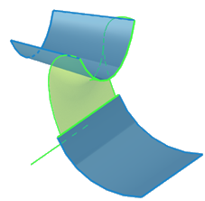
A supporting curve is a fundamental element of any variant of creating a transition surface. A supporting curve can be set by a 3D path, a route, an edge or several smoothly joint edges. Generating profiles which set the geometry of the surface to be created lie in the planes built perpendicular to the tangent lines whose direction is determined by the supporting curve. Generating profiles and the planes where they lie are invisible for the user. The picture shows how the supporting curve influences the generating profiles position (the profiles are shown symbolically as their real frequency is much higher).


Supporting curve can be located in any part of the 3D scene. The supporting curve should be located so as to avoid collisions of the end generating profiles, taking into account supporting curve curvature and the distance from it to other determining elements. In case the supporting curve is a segment, there will be no collision of the end generating profiles anyway, as they are parallel to each other. Besides, the supporting curve limits should be taken into account: no surface is built beyond them. The supporting curve can go beyond the limits of other determining elements.
Surface bend direction
The contact (bend) direction of the conic transition surfaces (the first three variants of surfaces) is determined by the position of the surfaces the directing curves belong to. The bending direction of the surface to be created is the only one possible in this case. The bending direction is determined by the tangent lines intersection point direction, the tangent lines being built to the surfaces in generating profile planes.


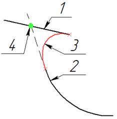

1 – the first surface; 2 – the second surface; 3 – the surface obtained (surface profile); 4 – tangent lines intersection point.
Free limit control
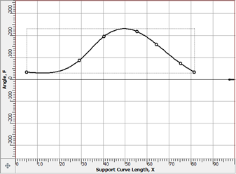
For Circle – Tangent to Surface, Circle – Radius transition surface variants the surface ends don’t depend on the geometric elements selected and are only determined by Angle parameter which can be constant or variable, set by the diagram. Variable values are set relative to the supporting curve length.


Accuracy parameters
All the variants of surface design have three accuracy parameters: Approximation Accuracy, Calculation Accuracy, Simplify Geometry.
Approximation Accuracy. Determines the partition accuracy for all the set curves: the supporting, the axial, the directing ones etc. The parameter sets maximal distance from the chord built between two adjacent partition points to the curve. The number of partition points determines the number of generating profiles. By default, partition accuracy parameter equals 0,0001 m.
Calculation Accuracy. Determines the approximation accuracy of generating profiles and the accuracy of joining adjacent generating profiles with a surface. By default, calculation accuracy parameter equals 0,00001 m. The given value allows us to obtain correct surfaces in most of the cases. It is not recommended to change the parameter if there are no visible problems with the design.
Simplify Geometry. Determines the surface edges type: the surface edge can be a single curve (if the flag is on) or a sequential set of edges (if the flag is off). By default the flag is on. The number of edges is one less than that of the generating profiles.
Use Guides. A directrix is a curve defining characteristic points of the generating profiles: a generating profile passes every characteristic point of the directrix (see explicative schemes of “Transition surface types” subsection). Besides, a directrix can set final surface shape between two adjacent generating profiles. If the flag for this option is on, the directrix shape at the section between every two adjacent profiles is used when building a joining surface (between the two points of the directrix which define generating profiles geometry). If the flag is off, the section between two characteristic points of the directrix (profile setting points) is approximated by some function which can be of a shape different from that of the directrix section discussed. It is obligatory that the approximation function passes the directrix points which set the profiles.
By default the flag is on.
In case a conic section surface is built (the first four variants of creating a surface), the directing curves shown as 2 and 4 at the schemes clearly set the shape between generating profiles, so it is not recommended to switch off this option for these construction variants.
In case the directrix is set from one end only or if it is not explicitly set but is defined from the construction, e.g. as in the fifth construction variant with circular profiles surface contact, switching the flag off can ensure a better result for the user. In the case cited (and in similar cases) the directrix is set at one side and is defined from the construction as a joining curve by circle contact points, it lies in the given contact plane which can influence the surface symmetry and curvature. Therefore it is acceptable to remove the flag and use directrix approximation at the sections between profiles instead of the directrix.
Angle Tolerance. The parameter is only available for Line – Tangent variant. The parameter determines the acceptable angle between the generating profile (segment) and tangent lines to the selected surfaces at the ends of the segment. By default the value equals 1°. The minimal acceptable value is 0,1°. It is not recommended to set angle tolerance less than 0,3° in terms of calculating resources saving.
Options
There is an additional feature enabled by default among the options: Dynamic preview. The option is standard for all the 3D Design commands. It gives a simplified representation of the surface being created which dynamically changes with initial parameters change.