Gusset |
  
|
To build stiffening ribs at sheet bodies Gusset operation is used:
Icon |
Ribbon |
|---|---|
|
Sheet Metal (3D) > Operations > Gusset |
Keyboard |
Textual Menu |
<SMG> |
Operation > Sheet Metal > Gusset |
The operation enables users to build stiffening ribs (gussets) at a given pitch, of a given number, of different types including ones made by user 3D profile. There are two variants of cross sections available for the gussets and the bending angles can be also different.

Gusset positioning and their number are set according to the chosen construction variant which is set by icons in operation parameters window.
|
By Point |
|
Fit |
|
Fill |
|
Step |
Another set of icons determines the gusset cross-section shape.
|
Round |
|
Square |
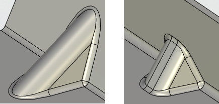
Gusset shape from the side is linear by default but it can be set basing on the user profile with the help of ![]() option.
option.
|
|
Gusset of a standard linear shape |
Gusset based on user profile |
Command parameters
Number, Step and Offset. The parameters determine the position and number of gussets at the given bend. Depending on the chosen construction variant these parameters can be available or closed.
•By Point. Number and Step parameters are closed for this construction variant. The gusset position at the bend is determined by the Offset parameter with a manipulator in the 3D scene. The Offset parameter determines the distance from the chosen face to the center of the gusset cross section. The face from which Offset parameter counting starts is determined automatically by the system. To change the position counting face, use ![]() option and choose another face or a plane.
option and choose another face or a plane.
•Fit. In this construction variant only Number parameter is available. The number of gussets set is uniformly distributed (the pitch is calculated automatically and is the same) along the bend.
•Fill. Only Step parameter is available in this variant. Number parameter is calculated basing on maximum possible number of copies. Offset parameter is equal to the pitch. The distance to the center of the last gusset to the end of the bend depends on the pitch and number of copies, so the displacement counting face swap option ![]() influences the result.
influences the result.
•Step. For this variant Number and Step parameters are available. Offset parameter is equal to the pitch. Changing the face of the reference - affects the result.
Depth, Width, Taper Angle, Punch Radius and Die Radius determine gusset geometry. Depth parameter is not available in case the gusset shape is set by user profile. Punch Radius parameter is not available in case of using a cross section of a round shape.
Command automenu options are:
|
<Ctrl>+<Enter> |
Finish input |
|
<P> |
Set entity Parameters |
|
<X> |
Exit command |
|
<F5> |
Preview Operation Result |
|
<A> |
Select Bend Face |
|
<F> |
Select Gusset Shape |
|
<Q> |
Select Plane |
|
<W> |
Draw Profile |
Finish input. To build geometry according to the given parameters. In case the parameters are insufficient, the option in not available.
Set entity Parameters. Call a standard 3-D design command parameters dialog.
Exit command. Shuts down the command canceling the given parameters.
Preview Operation Result. The option enables/disables a standard option for reviewing 3-D design commands.
Select Bend Face. Choosing the bend (cylindrical face) between two surfaces where it is necessary to build the gusset. The option is active by default.
Select Gusset Shape. The option determines the gusset shape from the side. Gusset shape can be set by profile, path or trace. The element determining gusset shape must lie in the plane perpendicular to the faces on which the gusset is built.
Select Plane. The option to choose the plane determining the origin. Either a face or a plane can be chosen. Displacement determines the distance from the selected plane or face to the center of the gusset cross section.
Draw Profile. The option enables you to build a profile in the transparent mode.
Creating a gusset
A typical procedure for creating a gusset is:
•Choose a bend face
•Choose the gusset cross section variant
•Choose the gusset shape profile (in case when other than linear shape is required)
•Set geometric parameters of the gusset
•Choose the variant to enter gusset position and number
•Change the origin plane (if necessary)
•Enter the gusset position and number parameters
•Finish entering.