Parametric 3D Fragment in Assembly |
  
|
Upon selecting the file, the parameters window is filled with parameters of the 3D fragment. One of its groups deals with external variables. The external variables can be displayed as a list – just as in the variable editor. If a custom dialog was created for managing external variables, it will be automatically built in the 3D fragment parameters window. If necessary, you can switch between the two modes of displaying the external variables. This is done by toggling the List of Variables flag in the parameters window.
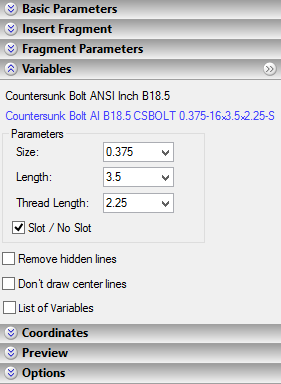
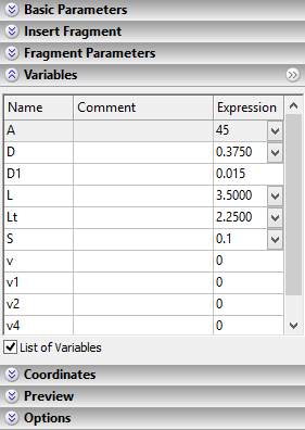
The information about external variables is displayed as long as the 3D fragment creation command is active. You can modify at any time the values copied from the fragment file. To update the 3D window for the changes in the parameters window, use the provided button ![]() .
.
If you find it inconvenient to modify the values of the external variables in the property window (as, for instance, because of the large size of the custom dialog), you can put the group of variables into a separate window and enter changes there. Calling the separate window is done by using a special button at the upper right corner of the group.
If the 3D fragment model does not have any external variables, then, upon executing the 3D fragment insertion command, no tools are displayed for managing external variables.
When a 3D fragment is attached to a connector, the values of the fragment variables can be assigned automatically (see the Using 3D Connectors section).
Parametric relation definition
Defining relations between parts is the main task for designing parametric assemblies. It demands from the engineer understanding of the T-FLEX CAD tools for maintaining such relations. The first tool that you need to master is the variable editor. The variable editor itself or similar environment is used by the system in multiple occasions, as, for instance, when defining the values of the fragment external variables. Working with the editor, variables, functions and such is described in the Variable Editor chapter.
Here, let's review a simple showcase for relating part parameters in order to control them from the assembly model. Here we will skip the description of the steps that are not related to the parametric assembly creation (the description of creating part files, attachment, etc.).
Consider the task – to create a switchboard that includes the mounting plate and a set of switches. The switches can be of two types. The types of the switches differ in some dimensions, however, can be composed from the same parametric parts. The switch lever must snap to two positions "On/Off". The switch itself is made of the following separate parts - the body, the pin and the lever. These parts are parametric, as they rely on the necessary external variables. By using those we can create a parametric model of the switch, whose external parameters define the switch type and the lever position. We need to create a switchboard assembly by using this parametric model of the switch.
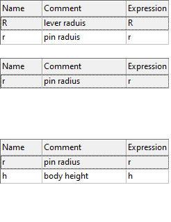
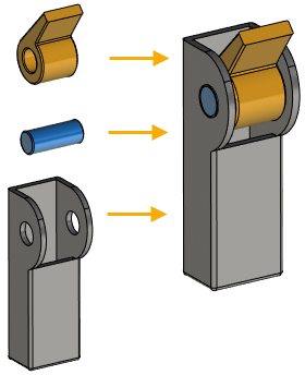
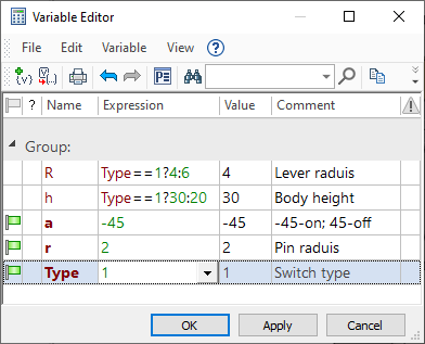
The upper illustration on the left shows the details of the switch. To the left of each part is a table of external variables of each part. These tables are taken from the dialog for setting external variables when inserting each 3D fragment. It can be seen that the corresponding assembly variables were substituted as the values of the external variables of the fragments (at this stage this is the switch file). The assembly model of the switch is shown in the right part of the upper illustration. The lower illustration shows variables from the variable editor. You can see on the diagram how the switch parameters are managed: the variables <R> and <h> change depending on the variable <Type> value that defines the switch type. The former two define geometrical characteristics of the contributing parts. The variable <a> is responsible for the lever position and defines the model property "On/Off". The external variable <r> will relay the pin radius value to the next assembly.
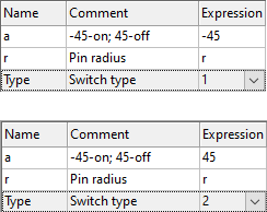
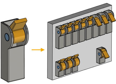
The next step is building the assembly (the switchboard) from the created parametric model of the switch. The left-hand side diagram shows the model of the switch and the two tables of its external variables with different values assigned when composing the assemblies. You can see from the diagram, that the variables <Type> and <a> are assigned numerical values, while the variable <r> is related, instead of a value, to the variable <r> of the assembly. This is how the parametric assembly is built. The variable editor of the switchboard provides control over the value of the switch pin radius.
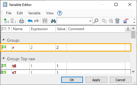
Other switch parameters are left fixed. To modify those in the future, you could call the command for editing 3D fragment variables.
When connectors are used, parametric relations between two parts can be established directly, skipping the step of creating the common variable in the assembly. At the same time, the variables of the new part, attached to the connector of another part already inserted into the assembly, will depend only on the values of the first part's variables (see the Using 3D Connectors section).