Splitting Methods of Imprinting Elements |
  
|
Projection by direction
In this method, the imprint tools are mapped on the imprint target objects along the specified direction.
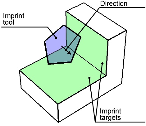
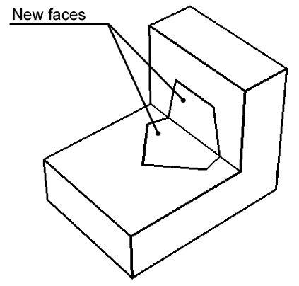
In this method, you need to specify the imprint tool and the imprint targets. Additionally, you need to specify the mapping direction. If the imprint tool is a flat 3D profile, then the assumed direction is along the 3D profile normal. Make sure that the profile mapping direction is towards the imprint target objects. To use a different direction, specify it manually.

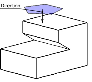
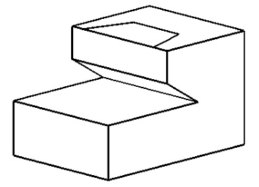
It is possible that the imprint tool mapping occurs along the surface, or even on the opposite side of the surface. In the Projection by direction method, upon selecting an imprint tool element, the option Connecting disjoint components appears for selecting the mode of joining edges in this case.
No means the system will attempt to create new edges only on the visible faces as viewed in the specified direction. Vertical means the system will attempt to create new edges on the faces visible in the specified direction or parallel to this direction. All means the system will attempt to create the edges on all faces, including the obstructed faces, as viewed in the specified direction. In this case, the new edges on the obstructed faces must allow a connection with new edges on other faces. The following diagrams show the results produced by each option.
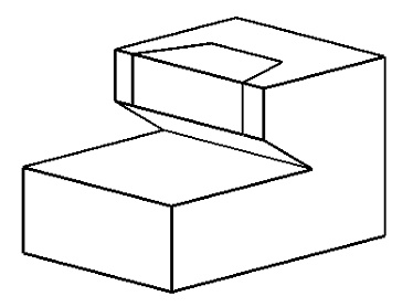
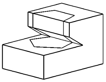
No Vertical All
Projection by normal
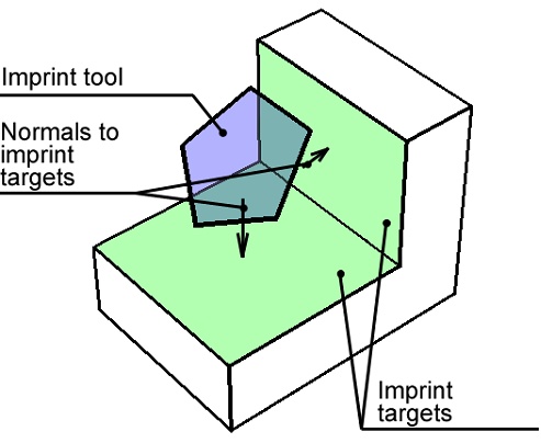
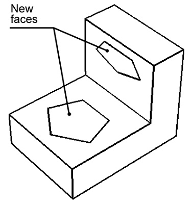
In this method, the boundaries of the new faces are determined by mapping the imprint tool objects on each imprint target object along the normal to the imprint target. All you need to specify is the imprint tool and target objects.
If the imprint target is not flat, the normal changes from a point to a point of the surface. In such a case, the imprint tool object is mapped on the target as follows: each point along the edges of the imprint tool is mapped onto the point of the target that is the origin of the normal passing through the point on the tool.
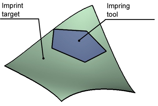
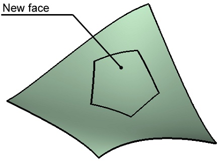
It is important that all points of the imprint tool had a unique mapping on the surface of the imprint target. The command will fail otherwise.
Intersection
In this method, the boundaries of the new faces are the intersection lines between the tool and the target objects.
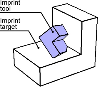
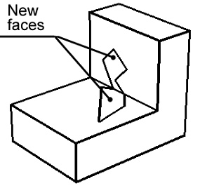
You need to specify the imprint tool and target objects.
If surface bodies are selected as the imprint target and tool objects, the combo boxes Imprint completion and Completion method appear in the parameters window.


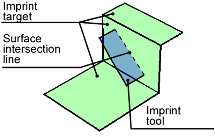
Those can be used in the case when the face of the tool surface body does not fully intersect the imprint target. In this case, setting Imprint completion to No results in no new edges created upon executing the command.
Alternatively, with the setting To nearest edge or To body boundary, the intersection line between the bodies will be extended (in the first case – up to the nearest edge, in the second – through all body), and that will be the edge.
The option Completion method lets you specify the direction of extending the edge: either tangent to the edge, or normal (reverse normal). The effect of each parameter is shown on the diagram below.
Edge extended up to the nearest edge |
Edge extended up to the surface body bound |
Tangent direction |
Normal |
Reverse Normal |
Projection as outline
In this method, the boundaries of the new faces are determined by the outline edges of the imprint target object.
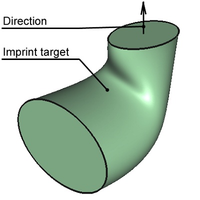
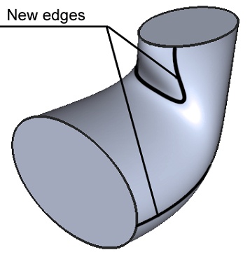
You need to specify the imprint target object and direction.
Create isoclinical curves
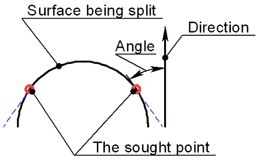
In this method, the boundaries of the new faces are determined by an isocline. An isocline is a line connecting points on the surface being split, in which the tangency line to the surface makes the same constant angle with the specified direction. In 2D, this can be easily sketched (see the right-hand diagram). In 3D, the system builds a set of points – a line.
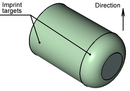
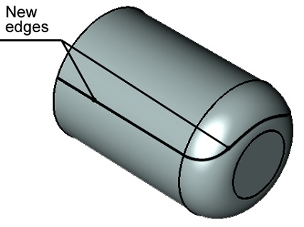
Isoclines are convenient in mold design. In some cases, an isocline is required for making Taper operation.