T-FLEX CAD - Features, interface, customization
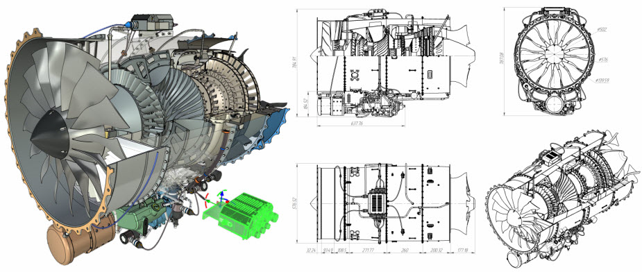
Friends! In the presented materials, we will introduce you to the basics of working in the T-FLEX CAD parametric system, on the basis of which you can fully work with the system and solve engineering problems. The system evolves, and design methods evolve with it. In an overview lesson, we will consider the features of the T-FLEX CAD system, its interface and basic settings required for comfortable and convenient work.
Let?s start!
So, what are the features that differentiate T-FLEX CAD from other CAD systems? Unified file format * .grb (* .grs - for the free student version) - one T-FLEX CAD document can simultaneously contain data on a 3D model (solids and surfaces), sheet metal, assembly (2D / 3D), drawings, etc. bill of materials, databases, macros, engineering calculations (CAE), CNC machining data (if a CAM module is installed), customized user interface:
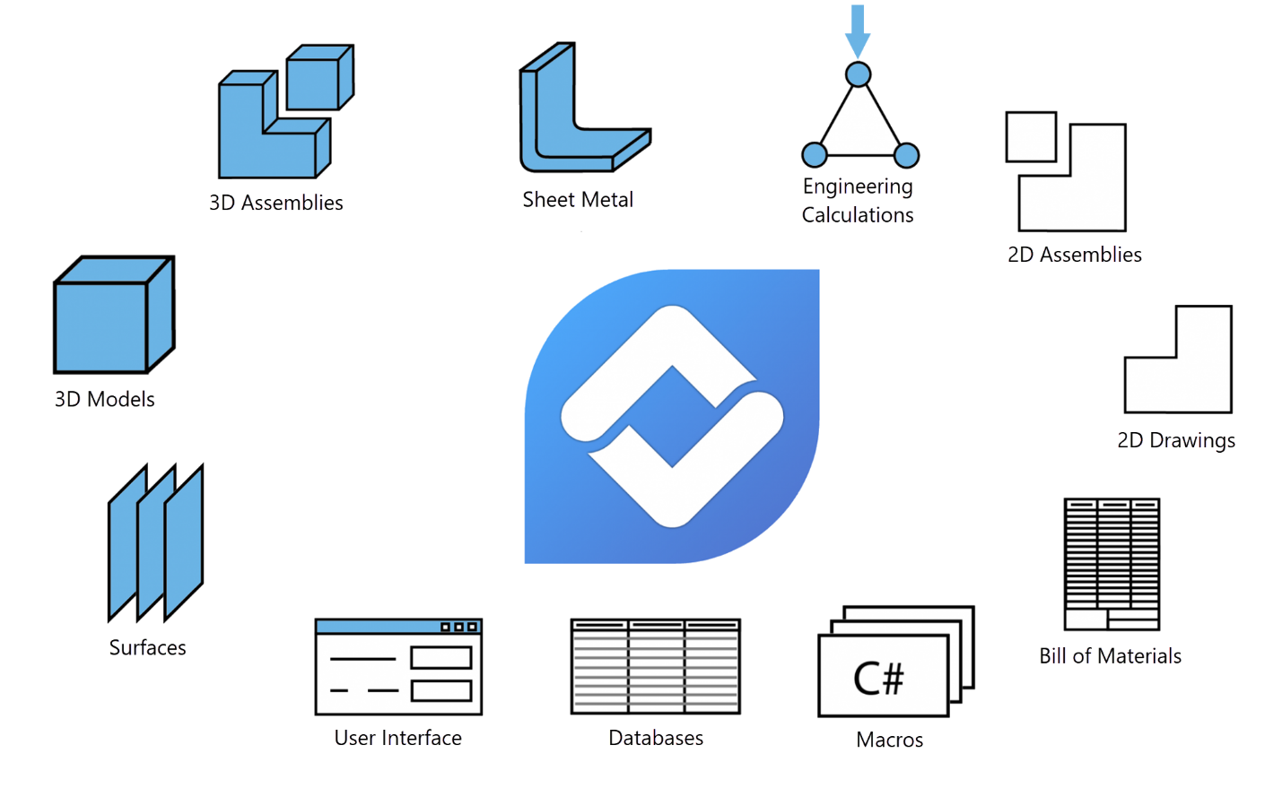
If necessary, different data can be stored in different files, as is customary in other CAD systems. For example, a 3D model, drawing and bill of materials.
T-FLEX CAD allows you to choose the most user-friendly interface type - ribbon (default) or toolbars with a textual menu:
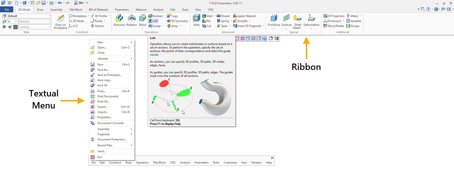
The interfaces can be used in parallel. Toolbars and windows can be moved anywhere in the working window. Any command or operation in T-FLEX CAD can be called using the keyboard. See the detailed video below.
Navigation in a 3D scene and drawing has its own peculiarities - rotation of a 3D model, for example, is performed with the left mouse button, by double-clicking the left mouse button, you can quickly complete any running operation in 3D, and by double-clicking on the mouse wheel, you can show the entire object in the 3D window. Many commands for modeling and 2D design, as well as visualization options, are located in dynamic toolbars. See the detailed video below.
T-FLEX CAD provides work with 2D and 3D in one document, as well as in multi-window and multi-page modes. See the detailed video below.
Moreover, you can simultaneously display a 3D model, drawing, database, graph editor and photorealistic image through a special interface:
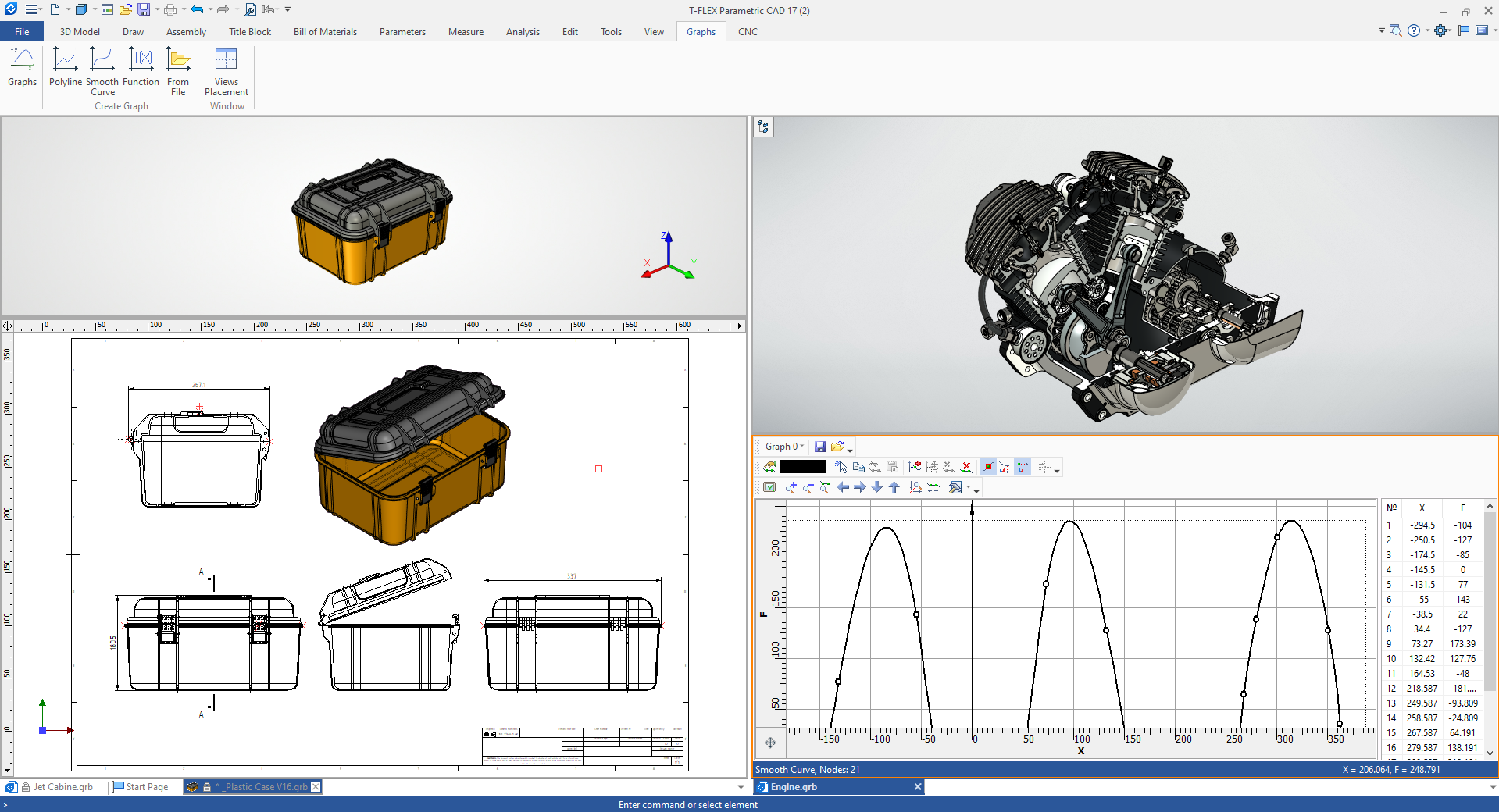
The transition to parallel work with 3D and 2D is carried out by simply pressing the button in the lower-left corner of the working window of the 3D scene:
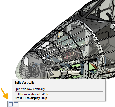
The system enables parallel modeling in 2D / 3D - when creating a 2D drawing, a 3D model is automatically generated.
And of course, T-FLEX CAD allows you to flexibly customize not only the interface, but also the parameters for working with the 3D model and drawing in accordance with ISO or ANSI, as well as perform system settings. See the detailed videos below.
Setting the parameters of the 3D model and drawing:
T-FLEX CAD provides an opportunity to use two ways of creating a 3D model - direct modeling in a 3D window and creating a 3D model from a finished drawing that can be imported from another system (for example, * .dwg format). We will analyze the purpose of each method and features of use in separate lessons.
Total parametrization of any system parameters, the ability to create your own control dialogs for parametric projects:
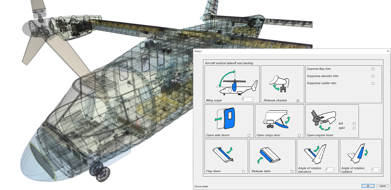
T-FLEX CAD provides a choice (or for joint use) two ways to parameterize a sketch - construction lines and constraints with driving dimensions:
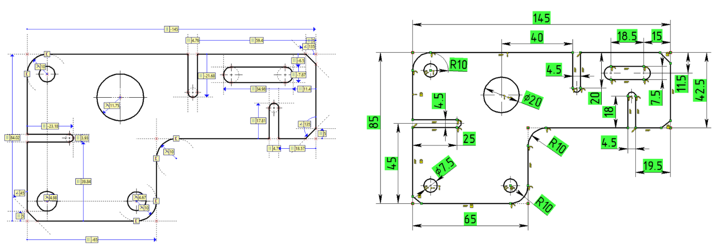
We will analyze both methods of parameterization in separate lessons.
T-FLEX CAD is distinguished by a powerful variable editor and an interface for working with databases for creating parametric models and assemblies:
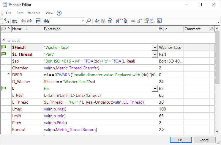
And of course, T-FLEX CAD allows you to flexibly customize not only the interface but also the parameters for working with the 3D model and drawing (in accordance with ISO and ANSI), as well as perform system settings.
In subsequent lessons, most of the information will be presented in the form of a description with pictures along with video files.
We hope that the information presented will be useful for completing the first steps to work with T-FLEX CAD!