T-FLEX CAD - Beginning of work. Modeling in 3D scene. Reference Elements
Friends! In the last lesson on working with T-FLEX CAD 17, we introduced you to the feature, interface and program settings. All the steps described in the lessons can be performed in the free T-FLEX CAD Student Edition.
In this lesson, you will learn what a workplane and worksurface are, how you can create a drawing on a workplane, and how to turn a model contour into a 3D model. It will also describe how to quickly copy, symmetry, or use reference geometry elements as arrays.
Reference 3D geometry is the basic T-FLEX CAD elements, on the basis of which a 3D model is created. Elements of 3D reference geometry include 3D Profiles, 3D Paths, 3D Nodes, etc.
3D model can be created in various ways, one of them is creating the base of a future model on a workplane. The workplane is the space-oriented plane to which 2D and 3D model elements are associated. At the beginning of work in the 3D scene, three standard workplanes are displayed - Left View, Front View and Top View. You can create additional standard workplanes at any time.

In addition to creating standard workplanes, you can create a plane along an edge, along a point, along another plane, etc. Thus, the workplane is the starting element for creating 3D elements.
In addition to workplanes, worksurfaces can be created in the system. Worksurfaces are auxiliary 3D elements that represent an image of a geometric surface of a certain type. A sphere, a cylinder, and a torus can be used as such surfaces.

Let's go back to creating a 3D model. To create any shaping operation - rotation, extrusion, lofted body, etc. - you need to create a contour that can be rotated about a selected axis or extruded out at a specified distance. Such a contour is called a 3D Profile. In order to form a 3D Profile, it is necessary to create its base on the workplane, worksurface, face or surface of an already created body in the scene. The command Draw ... is intended for this. The command can be invoked in several ways, one of them is from the 3D Model ribbon tab:

In this case, the system prompts you to select a face, workplane, or surface to draw.
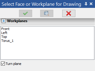
You can also call the drawing command from the context menu of a specific element ...:

... or using a dynamic toolbar that is invoked by clicking on the required element:

After activating the command, the system enters the drawing mode, where the base for the 3D Profile is formed.
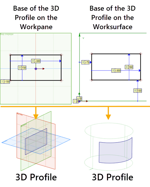
If you delete the base of the 3D Profile, then the 3D Profile itself will also be deleted. If you delete the 3D Profile, then its base on the workplane will be preserved. This means that the 3D Profile and its base are two different objects. 3D Profile is displayed in the 3D Model window:

At any time, the 3D Profile can be edited by calling the editing command in the 3D Model window:

In T-FLEX CAD, there are two ways to create a base for a 3D Profile:
1. The main and most functional way is construction lines with outline of graphic lines. With the help of construction lines, a "skeleton" of the base of the 3D Profile is created, which contains both dimensions and constraints. The constructed "skeleton" is outlined with the help of the graphic lines and a 3D Profile is formed on the basis of these graphic lines. To work with the described technique, the groups of commands for Construct and Draw are used:

2. The second method is using sketch elements, constraints and driving dimensions - the method adopted as the main one in most CAD systems. First, the base of the 3D Profile is created, constraints are imposed on it, and its dimensions are determined using driving dimensions. To work with the described technique, use the Sketch, Constraints command groups and the Dimension command:

3D Profiles can be single-contour and multi-contour. If there is one contour on the workplane, the profile is single-contour, if more - multi-contour:

On the basis of a multi-contour 3D Profile, a solid body is created, consisting of several shells. 3D Profile can be closed or open. A solid body is formed on the basis of a closed 3D profile, and a surface is formed on the basis of an open one.
In T-FLEX CAD, using shaping operations, you can create both solid bodies and surfaces.
Closed 3D Profile is formed using a closed 3D Profile base while an open 3D Profile is formed using an open 3D Profile base:

In the 3D Model window, the appearance of a solid body and a surface body is different:

If, for example, two contours of different colors are created on the workplane, then a separate 3D Profile will be created for each color:

3D Profile can also be defined by hatching. If the plane contains both hatching and graphic lines - the 3D Profile will be created from the hatching - it has higher priority. In some cases, hatching is convenient to use in common with construction lines:

When drawing on a face or workplane, you can rotate the 3D scene using a special option in the View toolbar:

To exit rotation mode, press the option again.
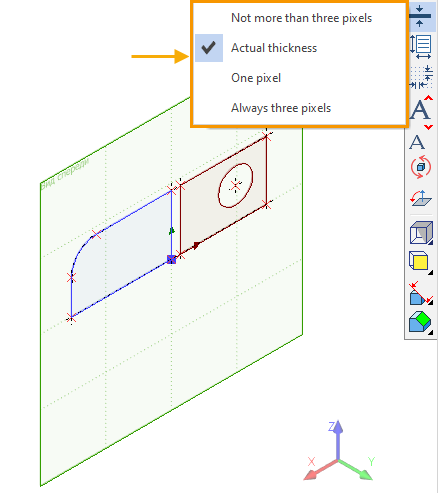
You can also change the thickness of the contour lines by choosing the options you need:
Let's consider a few more types of reference geometry. A 3D model can be created using 3D Nodes, 3D Paths or Route.

If the 3D scene has a Route and several 3D Nodes, then you can get a surface body by performing the Rotation operation, specifying two 3D Nodes as the axis of rotation:

In addition, the Route can be overlaid on various faces of the model:

If the 3D scene already has elements of reference geometry, for example, 3D Nodes, then on their basis you can create such basic elements as 3D Path and Helix 3D Path.

To create a 3D Path and a Helix 3D Path, at least two elements are required, for example, 3D Nodes:

Also the basic element of the system is the 3D Axis.

The command is intended to create 3D Axes based on surfaces of rotation and edges. There are several ways to create a 3D Axis.
The first way is to create an axis on the workplane. It consists on creating an axis line using one of the methods for constructing the base of a 3D profile described above:

After creating an axis line and exiting drawing mode, the 3D Axis will appear in the 3D scene:

The second way is to create a 3D Axis directly in the 3D scene. To do this, you need to specify the base element on the basis of which the 3D axis will be created:

Once created, reference geometry can be easily copied, flipped symmetrically, or used as an array. To do this, use the following commands from the 3D Model ribbon tab:

So, for example, by activating the 3D Symmetry operation and selecting the option Symmetry of Construction elements, you can easily display the previously considered elements of the reference geometry relative to the selected plane:
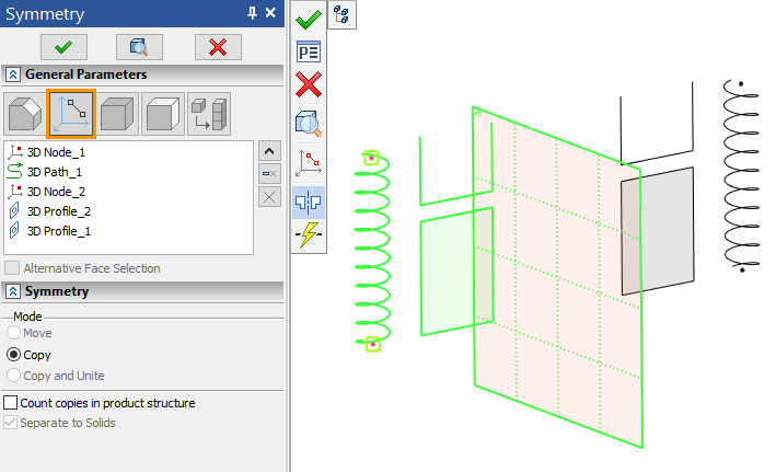
This completes the introduction to 3D Profiles and basic elements of 3D reference geometry.
You have learned that different elements of 3D reference geometry can be used in different ways. Thus, you can use 3D Profiles to create 3D models. 3D Nodes, 3D Paths or Route can be used, for example, to create a surface body.