3D Annotations |
  
|
3D Annotations |
|
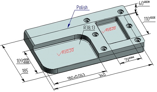
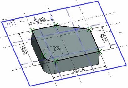
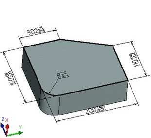
T-FLEX CAD allows creating drawing detailing elements (dimensions, leader notes, roughnesses) directly on faces of a 3D model.
General information
The capability of creating 3D annotations allows instantly introducing in the 3D model not only geometrical, but also technological process and other information that can later be used when creating drawings by projections, as well as in other applications, for example, in the process design modules or when creating CNC control sequences.
For example, if a dimension between faces or a dimension on a cylindrical face (radius or diameter) uses a tolerance or additional text lines, then, when creating the dimension in the drawing you select the respective lines on a projection - this information is automatically passed on to the dimension on the 2D projection. The same happens when creating a roughness symbol on a face – if you create a roughness symbol on the respective lines of the 2D projection image, then the roughness parameters will be copied from the 3D model.
Data transfer from 3D dimensions to a 2D projection can be done also by a direct "projection" (mapping) of dimensions from the 3D space onto the 2D projection. In this case, the system automatically determines, which of the existing 3D model dimensions can be "transferred" to the current 2D projection. The user just needs to select, which out to the system-offered dimensions one would like to put on this 2D projection. This functionality is described in detail in the chapter "2D Projections. Creating Drawings from 3D Models" (see the section "Creating Drawing Detailing Elements on 2D Projections").
3D dimensions can be used to manage dimensions of the 3D model. When creating various 3D operations, the systems allows for an automatic creation of "driving" 3D dimensions. A driving dimension is directly related with the operation that created it, or, more precisely, with its geometrical parameter. As soon as its nominal value is modified in the command "Parameters|Dimensions|Set Value", the respective parameter of the dimension-producing operation will change.
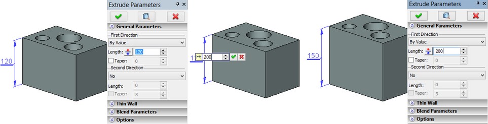
The driving 3D dimensions can also be created by the user manually. To do this manual dimension creation, select the faces, whose positions are determined by the operation's geometrical parameter. For example, you can use the opposite faces of a body created by extruding, or a cylindrical face created by blending. By using such dimensions, you can also modify the operation parameters and, therefore, the entire 3D model.
2D dimensions can also be used to modify an operation's parameter values, which are created between the lines of 2D projections that correspond to the body faces driven by that operation's geometrical parameter. The system finds this corespondence automatically.
Besides that, the system can in some cases automatically find correspondences between various 3D dimensions, which are not the control dimensions (the ones not related with the operation parameters), and 2D constructions used for the body creation, on whose faces those dimensions are based. This also allows managing the 3D model by modifying the nominal values of such 3D dimensions. When the nominal value of such a dimension is modified, the system will attempt to automatically find the 2D constructions, which shall be modified in order to accommodate for the new nominal value of the given 3D dimension. For example, if a 3D dimension is created between two side faces of a 3D profile extrusion operation, then the system is able in a number of cases to restore the constructions train: 3D profile а Profile contour on the workplane а 2D constructions that determined the 3D profile contour. In this case, as soon as the dimension nominal value is modified, the system will adjust the corresponding 2D constructions, the 3D profile based on them and the body itself, which resulted from the extrusion operation.
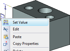
A 3D dimension nominal value is modified, just like that of a 2D dimension, by the command "PE: Set Dimension Values". Note that this command does not work on 3D dimensions in the transparent mode. It can be accessed, however, from any 3D dimension's context menu (on right-clicking it ![]() ).
).
3D annotations can be hidden or displayed in each particular window using the new command "SN: Hide 3D Annotations":
Icon |
Ribbon |
|---|---|
|
|
Keyboard |
Textual Menu |
<SN> |
View > Hide 3D Annotations |
Creating 3D Annotations
3D annotations can be created as follows:
● In the 3D window, using the common commands for creating dimensions, leader notes and roughness symbols ("D: Create Dimension", "IN: Create Leader Note", "RO: Create Roughness Symbol");
● As 2D detailing elements on workplanes and their consequent display in the 3D window.
Creating 3D Annotations in the 3D Window
Creating 3D Dimensions in 3D Window
To create a 3D dimension, call the command "D: Create Dimension" while in the 3D window.
3D dimension can be drawn:
-Between two planes. When choosing two planar faces, a linear dimension is drawn (for parallel planes) or an angular dimension - (for nonparallel planes);
-Between a plane and a line. A linear dimension is drawn if a line is parallel to a plane, and a radial one – otherwise;
-Between a plane and a point. A linear dimension is drawn between a given plane and a point;
-Between two lines. A linear dimension is drawn if the lines are parallel to each other, and a radial one – otherwise;
-Between a line and a point. A linear dimension is drawn between a given line and a point;
-Between two points. A linear dimension is drawn between selected points (vertices);
-On a single rotation surface. A radial/diametrical dimension is drawn for selected face.
The planes are specified by selecting a planar face or a planar curvilinear edge, the rotation surfaces – by selecting a face of revolution lying on the given surface. The lines are specified by selecting straight edges or the axes of the rotation surfaces. The axis of the rotation surface is specified by selecting the corresponding face of revolution. The points are specified by selecting vertices of the 3D model solid bodies and 3D nodes.
When creating 3D dimensions, the elements are selected with the help of the following auto menu options:
![]() <L> Select Flat Face or Flat Edge
<L> Select Flat Face or Flat Edge
![]() <C> Select Cylinder, sphere or torus
<C> Select Cylinder, sphere or torus
![]() <N> Select Vertex
<N> Select Vertex
![]() <A> Select Axis
<A> Select Axis
By default, in the 3D window the user can select planar faces, faces of rotation surfaces, edges and vertices of solid bodies without turning to the corresponding auto menu options.
If upon creating a 3D dimension, the user selects first the edge-circle/circular arc, or the face of revolution of type cylinder, sphere, torus, then the system will automatically start creating a radial/diametrical dimension. In other cases, the system will wait for selection of the second object (face, edge, vertex) for creating a linear or angular dimension.
For selecting the axis of the rotation surface (cylinder, sphere, torus) as the first object for creating a linear/angular dimension, it is necessary to use the option ![]() when choosing the face of revolution. The same option is used for selecting a planar edge-circle (circular arc) as the first object of the linear/angular 3D dimension.
when choosing the face of revolution. The same option is used for selecting a planar edge-circle (circular arc) as the first object of the linear/angular 3D dimension.
A dimension being created may lie in various planes. The initial position of the dimension being created is automatically determined by the system based on the 3D view. You can then modify the 3D dimension plane by the option:
![]() <H> Change 3D Dimension Orientation
<H> Change 3D Dimension Orientation
![]() <T> Select Plane of Orientation
<T> Select Plane of Orientation
The option ![]() allows one to cyclically switch between various dimension positions.
allows one to cyclically switch between various dimension positions.
The option ![]() is used for direct selection of the plane, to which the dimension being created has to be parallel. After turning on the option, in the 3D window the user has to select a face, to the plane of which a 3D dimension has to be parallel.
is used for direct selection of the plane, to which the dimension being created has to be parallel. After turning on the option, in the 3D window the user has to select a face, to the plane of which a 3D dimension has to be parallel.
When creating 3D dimensions, several standard options for setting dimension parameters are also available:
![]() <Z> Change leader line jog orientation (only for linear dimension)
<Z> Change leader line jog orientation (only for linear dimension)
![]() <Space> Place Dimensions in absolute coordinates
<Space> Place Dimensions in absolute coordinates
![]() <J> Center Dimension Text
<J> Center Dimension Text
![]() <Z> Change Dimension Orientation (only for angular dimension)
<Z> Change Dimension Orientation (only for angular dimension)
![]()
![]() <M> Change Dimension type (only for radial/diametrical dimensions)
<M> Change Dimension type (only for radial/diametrical dimensions)
![]() <D> Click to toggle radius/diameter mode (only for radial/diametrical dimensions)
<D> Click to toggle radius/diameter mode (only for radial/diametrical dimensions)
![]() <R> Click to toggle radius/diameter mode (only for radial/diametrical dimensions)
<R> Click to toggle radius/diameter mode (only for radial/diametrical dimensions)
![]() <К> Break (kill) relations (only for linear and radial/diametrical dimensions)
<К> Break (kill) relations (only for linear and radial/diametrical dimensions)
Creating 3D Leader Note and 3D Roughness in 3D Window
To create a 3D leader note or 3D roughness, you need, while in the 3D window, to call the command "IN: Create Leader Note" or "RO: Create Roughness Symbol". When creating a leader note/roughness, you select the face, on which the element being created shall be placed. The face can be of any type. The snap point of the leader note or roughness is the point on the selected face where the cursor was positioned at the time of selecting the face. For a leader note, you need to additionally specify its jog position in the space.
Other than that, creating 3D dimensions, 3D leader notes and 3D roughness symbols is same as creating the respective 2D elements.
Creating 3D Annotations by 2D Detailing Elements on a Workplane
To create 3D annotations by 2D elements on a workplane, you need to first create the respective 2D dimensions, leader notes, roughness symbols on the page of the workplane. To display them in the 3D window, you just need to enable the flag "Show 2D Annotations on 3D View" in the workplane parameters dialog box.
For working convenience, this option is also available in the context menu of the plane ("Show Dimensions in 3D").
Such dimensions can be used for modifying the display parameters on the workplane page and, respectively, the 3D elements created based on it (profiles, operations etc.). They can also be used for auto-dimensioning projections (under condition that the workplane is parallel to the projection plane).
Automatic Creation of 3D Dimensions
Automatic creation of driving 3D dimensions, that is the 3D dimensions related with the geometrical parameters of 3D operations, is made either directly when creating the operation, or from the context menu of an already existing operation.
When creating a 3D operations, you just need to enable the flag "Create Driving Dimensions" in the operation's properties dialog (the "Options" section). The driving 3D dimension will appear in the 3D window once this operation creation is completed.
If an operation was already created, call the context menu (by right-clicking ![]() ) and select the "Create Driving Dimensions" command in it. This will also result in creating a 3D dimension that controls the geometrical parameter of the given operation. If several operations are selected, then you can still access the control 3D dimension creation command in the context menu. This command is also available in the Body's context menu. In the latter case, the control 3D dimensions will be created in all operations used for creating the Body, wherever possible.
) and select the "Create Driving Dimensions" command in it. This will also result in creating a 3D dimension that controls the geometrical parameter of the given operation. If several operations are selected, then you can still access the control 3D dimension creation command in the context menu. This command is also available in the Body's context menu. In the latter case, the control 3D dimensions will be created in all operations used for creating the Body, wherever possible.