Creating and Editing Drawing Elements |
  
|
Creating and Editing Drawing Elements |
|
The system provides a specific command for creating and editing each type of model elements. This section describes main concepts of using these commands, as well as general principles of creating and editing a 2D drawing.
Snapping Mode. Snap Types
T-FLEX CAD system supports two distinct modeling modes:
●One is free mode in which the elements are selected within commands using the automenu and the keyboard.
●The other, object snapping mode, provides pre-highlighting of the elements available as references in element creation and editing commands. The latter mode is enabled by default on starting the application.
The pictogram ![]() , located on the toolbar “View”, controls the snapping modes. Use this icon to enable or disable the object snapping mode.
, located on the toolbar “View”, controls the snapping modes. Use this icon to enable or disable the object snapping mode.
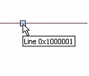
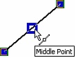
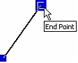
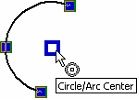
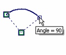
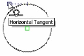
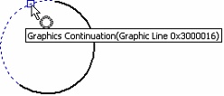
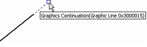
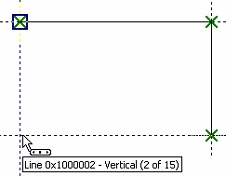
An element is pre-highlighted in the object snapping mode as the cursor approaches the element. Meanwhile, the cursor itself gains a mark corresponding to the pre-selected element, and a popping up help message displays the name and Id of the element. On the screen this looks like the following diagram:
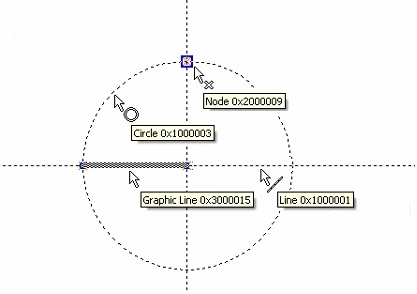
The pre-highlighted element can be selected using the mouse. This relieves the user from using the automenu or the keyboard in most cases.
Various construction and graphic elements are pre-highlighted in creation and editing commands only when it makes sense. Thus, for instance, in spline creation, only nodes will be pre-highlighted, as the spline is created based on a set of nodes. No other elements will be pre-highlighted on cursor approaching, as this does not make sense for spline creation.
Please note that the current documentation refers to the element selection mode with disabled object snapping when describing commands (implying only the use of automenu options).
To temporarily disable object snapping within a command, hold the <Ctrl> key down. Snapping is suspended as long as the key is held.
When defining positions of various 2D elements in their creation/editing commands, with the object snapping enabled, not only can you use the existing elements (construction lines, graphic lines, nodes etc.), but also select characteristic points defined by object snaps. Nodes can be automatically created in the selected points. Those could be nodes at intersection of construction lines, nodes from fragments, nodes on dimensions, leader notes, tolerances and text entities, nodes aligned vertically/horizontally with another 2D node, nodes at the center of a graphic circle line or circular arc, etc.
The most number of object snaps is used in the sketch-creating command "SK: Create Sketch". Some of the object snaps may be unavailable in other 2D commands. Besides that, the use of snaps is affected by the settings made in the command "SO: Set System Options". You specify what snap types can be used when working with a 2D drawing on the "Snaps" tab of this command. There you can also set the priority for each snap. Snap priorities determine, in what order the system will offer them to the user (in the cases when several snap choices are found). A detailed description of setting up snaps in the command "SO: Set System Options" is given in the chapter "System setup".
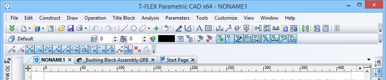
Most of the object snaps can also be managed using the specialized "Snaps" toolbar. By default this toolbar is “hidden” inside the toolbar “View”. To get an access to this toolbar, press the button ![]() .
.
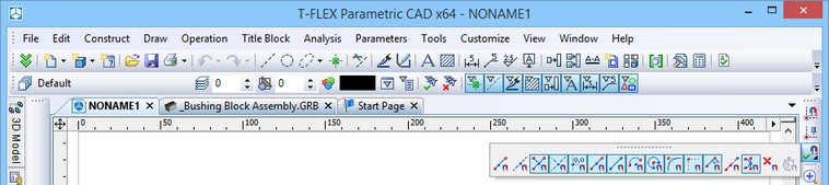
For displaying this toolbar in an “independent” mode, move the cursor to the title area of the toolbar, press ![]() and, without releasing the mouse, drag the toolbar into the desired location. In the future this toolbar can be left in the floating mode or snapped at any place of the T-FLEX CAD window.
and, without releasing the mouse, drag the toolbar into the desired location. In the future this toolbar can be left in the floating mode or snapped at any place of the T-FLEX CAD window.
Using this toolbar, one can set and unset the snapping modes by clicking the desired icons with ![]() . All snappings can be simultaneously turned on or off by the button
. All snappings can be simultaneously turned on or off by the button ![]() - “Clear all sketch Snaps”. Also, all snapping modes except the required one can unset by clicking appropriate icon with <Ctrl> button pressed.
- “Clear all sketch Snaps”. Also, all snapping modes except the required one can unset by clicking appropriate icon with <Ctrl> button pressed.
Listed next are the main types of object snaps used in T-FLEX CAD:
-Snapping to a point on a graphic line or construction line – ![]() ,
, ![]() ;
;
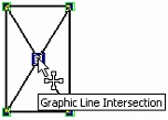
-Snapping to graphic line intersection – ![]() ;
;
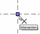
-Snapping to construction line intersection - ![]() ;
;
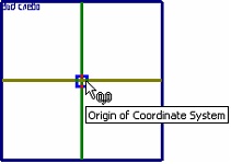
-Snapping to the coordinate system origin ((0,0) point) – ![]() ;
;
-Snapping to the midpoint of the graphic line – ![]() ;
;
-Snapping to graphic line end points – ![]() ;
;
-Snapping to the center of an arc or circle – ![]() ;
;
-Snapping to arc angles 90°, 180°, 270° – ![]() ;
;
-Vertical/horizontal tangency to circle – ![]() ;
;
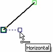
-Cursor becoming aligned horizontally or vertically to another element point or 2D node – ![]() ;
;
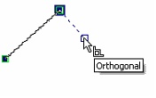
-Automatic definition of a line normal – ![]() ;
;
-Cursor becoming aligned to the extension of a graphic line – ![]() ;
;
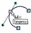
-Automatic definition of a tangency to an arc or circle – ![]() .
.

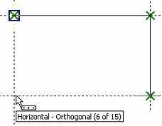
In the creation/editing process, the system automatically finds the allowed snaps and offers them to the user (by flashing a snap type next to the cursor). Besides that, the system monitors for a coincidence of two object snaps, for example, vertical – horizontal, perpendicular – horizontal, etc.
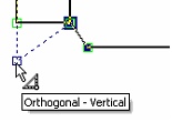
If several object snap choices are found at a given point, the system lets the user select the desired snap (or a combination of two snaps). To do this, you need to place the cursor at the desired location and rest it for a while. Then the cursor changes its appearance: the mark ![]() appears next to it together with a tooltip showing the total number of object snaps found by the system. Use the mouse wheel to scroll through those snaps. Clicking
appears next to it together with a tooltip showing the total number of object snaps found by the system. Use the mouse wheel to scroll through those snaps. Clicking ![]() determines the snap that will be used in the creation or editing of the current 2D element.
determines the snap that will be used in the creation or editing of the current 2D element.
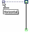
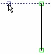
A system-offered object snap can be locked by the <Spacebar> function key.
For example, let's fix horizontal snapping to one of the segment nodes. To do this, get horizontal snapping with this node and press the key <Shift> or <Spacebar>. A temporary dotted line will be constructed through this node, the cursor sliding along as a free node.
Snapping that are turned on on the sketch snapping toolbar stay active continuously throughout the sketch command session. If snappings are adjusted often, one can use temporary object snappings -the "one-action" snappings.
Such a snapping can be turned on by several means:
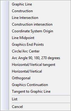
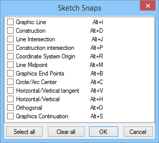
● By the button ![]() on the snappings toolbar. This brings up a context menu for specifying a temporary snapping (just one); it also lists key combinations that can be used for invoking a temporary snapping without calling the menu. To define several temporary snappings, use the item [List]. Upon picking the item, the context menu is replaced by a dialog box that allows turning on several temporary snappings simultaneously.
on the snappings toolbar. This brings up a context menu for specifying a temporary snapping (just one); it also lists key combinations that can be used for invoking a temporary snapping without calling the menu. To define several temporary snappings, use the item [List]. Upon picking the item, the context menu is replaced by a dialog box that allows turning on several temporary snappings simultaneously.
● By pressing and releasing the middle mouse button or the wheel button while keeping the mouse pointer still in the working window area. As a result, the same menu will appear on the screen as when using ![]() .
.
● By pressing key combinations assigned to each snapping.
When temporary object snapping is turned on, all permanent snappings are ignored. The described temporary snappings act until the first click ![]() .
.
Using Grid
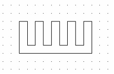
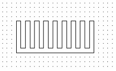
When creating a drawing, it is sometimes helpful to use a grid of dots. In this way, snapping will occur to the grid dots while creating various drawing elements. The precision with which you create drawing elements can be controlled by specifying the appropriate grid step.
The grid can be turned on for the active page by the command "QG: Change Grid Settings":
Icon |
Ribbon |
|---|---|
|
Edit → Document → Grid |
Keyboard |
Textual Menu |
<QG>, <ALT><F6> |
Customize > Grid |
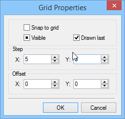
The following required parameters are defined in the Grid Properties dialog box:
Visible. Sets the display mode of the grid. The grid color is defined in the system options (the "SO: Set System Options" command).
Snap to grid. Sets the element snapping to grid mode.
Drawn last. Defines the order of drawing the grid on screen.
Step X. Defines the grid step along the X-axis of the drawing.
Step Y. Defines the grid step along the Y-axis of the drawing.
Offset X. Defines the grid shift along the X-axis of the drawing with respect to the origin (0,0).
Offset Y. Defines the grid shift along the Y-axis of the drawing with respect to the origin (0,0).
The grid options are saved with the drawing.
The grid management commands are accessible via the textual menu "Customize|Snap":
![]() <Ctrl><G> Grid Snap On
<Ctrl><G> Grid Snap On
![]() - Enlarge Grid Step (doubles)
- Enlarge Grid Step (doubles)
![]() - Reduce Grid Step (halves)
- Reduce Grid Step (halves)
If the grid snap is turned on then the grid knots serve as the snapping nodes for the drawing elements.
General concepts of element creation
Placement of any element on the drawing can be defined in the following ways.
Independent of other elements. This kind of placement is defined by the absolute coordinates of the element on the drawing, independently of other element locations.
Placement of such elements is usually set by clicking ![]() or by assigning exact values of snapping coordinates in the command’s properties window.
or by assigning exact values of snapping coordinates in the command’s properties window.
Dependent on reference elements. The element location will depend on the location of the reference element this one is related to. When the location of the reference elements is modified, the current element will relocate accordingly.
To select the reference elements to snap to, the options are provided for selecting a line, a circle, a node, etc. in most 2D element creation commands. The variety of available options depends on the element being created. The most commonly used snapping options are presented below:
![]() <L> Select Line
<L> Select Line
![]() <C> Select Circle
<C> Select Circle
![]() <N> Select Node
<N> Select Node
![]() <E> Select Ellipse
<E> Select Ellipse
![]() <S> Select Spline
<S> Select Spline
When the object snapping is on, use of these options is not essential. However, using the options in this case helps narrow down the range of elements available for snapping. Thus, for instance, with the option ![]() active, only circles will be pre-highlighting when moving the cursor around the drawing.
active, only circles will be pre-highlighting when moving the cursor around the drawing.
When creating and editing elements, an earlier created relation of this element with another element can be abolished by the following option:
![]() <K> Break (kill) relations
<K> Break (kill) relations
Object snaps can be used in both ways of defining the 2D element position. The set of the available snaps depends on the current command. By using snaps, a 2D element being created can be tied to:
- a free 2D node automatically created at the specified location (that is, not tied to objects used for snapping);
- a tied (constrained) 2D node automatically created at the specified location (the tie of the node with the source elements is maintained);
- in free coordinates (snaps define only the absolute coordinates of the element being created).
Tied nodes are always created when having snaps to a construction line intersection, circle center, end points of graphic lines, characteristic points of drawing annotation elements (dimensions, leader notes, roughness symbols, tolerances), as well as 2D fragments.
When using all other snap types, the status of the auto-parameterization mode is regarded (the icon ![]() on the “View” toolbar). If the auto-parameterization mode is enabled, then a tied node is created. Upon disabling the auto-parameterization mode, either a free node is created, or a point is picked with appropriate coordinates (when creating a leader note, roughness symbol, tolerance, section view and 2D fragments).
on the “View” toolbar). If the auto-parameterization mode is enabled, then a tied node is created. Upon disabling the auto-parameterization mode, either a free node is created, or a point is picked with appropriate coordinates (when creating a leader note, roughness symbol, tolerance, section view and 2D fragments).
Most creation commands allow setting parameters of all newly created elements. To do that, parameters need to be set right after the input of the command, before the start of element snapping and assigning its location. Assigning parameters can be done in either command’s properties window, or in a special parameters’ dialog box, called by the following option:
![]() <P> Set parameters
<P> Set parameters
The parameters of a particular element being created can be defined in the command's properties window during its creation. One can also use the option ![]() , but only if calling it during an element creation process after defining its position and snapping.
, but only if calling it during an element creation process after defining its position and snapping.
Commands for creating some of the 2D elements (dimension, roughness, leader note) provide option of assigning parameters from already existing element of the same type:
![]() <Alt+P> Copy Properties from Existing Element
<Alt+P> Copy Properties from Existing Element
Values of the copied parameters can be set as default parameters (parameters that will be assigned to the newly created elements of this type).
Any creation or construction command allows calling the editing command from within, using the option:
![]() <F4> Execute Edit Element command
<F4> Execute Edit Element command
You will return into the original element creation or construction command after completing editing in the editing command.
Canceling an element selection performed within a creation or editing command is done by the option:
![]() <Esc> Cancel selection
<Esc> Cancel selection
This option does not cancel the command itself.
To quit a command, use the option:
![]() <Esc> Exit command
<Esc> Exit command
General concepts of editing elements
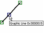
In editing commands, element selection is done by the cursor. To select, move the cursor to the element and click ![]() or press <Enter>. Different elements are highlighted in different ways. Some are painted with colors, others surrounded by a frame. To relocate a selected element, move the cursor to the desired position and click
or press <Enter>. Different elements are highlighted in different ways. Some are painted with colors, others surrounded by a frame. To relocate a selected element, move the cursor to the desired position and click ![]() . The element will relocate (if the method of its snapping allows that).
. The element will relocate (if the method of its snapping allows that).
If a wrong element was selected, cancel the selection with the option:
![]() <Esc> Cancel selection
<Esc> Cancel selection
or select the next nearest one using the option:
![]() <I> Select Other Element
<I> Select Other Element
The subsequent elements of the given type can be selected by using this option repeatedly.
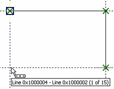
In editing commands, the user can select multiple elements using box selection. To do so, move the cursor to the intended location of one corner of the box, press and hold ![]() , and drag the cursor to the location of opposite corner of the box, then release. If the cursor was moved left-to-right when marking the box, all elements that are fully within the specified region are selected. In this case the selection box is painted with a green color. If the cursor was moved right to left, the objects are selected by the crossing frame. That means that not only the objects that are entirely within the selection box, are selected, but also the objects intersected by the box. In this case the selection box is painted with a pink color.
, and drag the cursor to the location of opposite corner of the box, then release. If the cursor was moved left-to-right when marking the box, all elements that are fully within the specified region are selected. In this case the selection box is painted with a green color. If the cursor was moved right to left, the objects are selected by the crossing frame. That means that not only the objects that are entirely within the selection box, are selected, but also the objects intersected by the box. In this case the selection box is painted with a pink color.
A group of elements can also be selected by subsequent picks with the <Shift>+![]() combination. An element can be excluded from selected by picking it with the <Ctrl> +
combination. An element can be excluded from selected by picking it with the <Ctrl> +![]() combination.
combination.
All existing elements of the given type can be selected at once using the option:
![]() <*> Select All Elements
<*> Select All Elements
Selecting an element from a list is done using the option:
![]() <R> Select element from list
<R> Select element from list
The list can be composed differently for elements of different types. For instance, when editing fragments, the list will contain all model fragments, while when working with nodes, the list will contain only the named nodes.
All editing commands allow deletion of a single or multiple selected elements, using the option:
![]() <Del> Delete selected Element(s)
<Del> Delete selected Element(s)
The following option is available within common 2D element editing commands:
![]() <O> Create Name for selected Element
<O> Create Name for selected Element
This option allows assigning a name to the selected element. The name is a unique attribute of an element and can be used, for instance, for searching elements using the command "FD: Find Element", for selecting elements in a list, and for creating nodes from fragments within the "EN: Edit Node" command. When the entered name is the same as a one already assigned to another element, the system will output the message "Incorrect Element Name or Name already exists".
The 2D node editing command allows assigning names to multiple selected nodes simultaneously. In this case, the names are made by appending subsequent numbers to the entered name, for instance, "name1", "name2", etc.
When 3D elements are constructed or created, the system assigns them "default" names. If necessary, the user can change a name in the element parameters window.
Editing commands allow the user to change selected element parameters. This can be done directly in the command properties window (just like at the time of creating this 2D element), if only one element was selected for editing.
If several elements are selected, use the option:
![]() <P> Set parameters
<P> Set parameters
After calling the option, a dialog box comes on screen first, offering to select the parameters to be modified. Next, the parameters dialog appears. Any changes to parameters not selected for editing in the previous dialog, will be ignored. Some parameters of the selected elements can be modified using the system toolbar.
When editing dimensions, roughness symbols, leader notes, just like at the time of their creation, you can copy parameter values for the edited element from another element of the same type, using the option ![]() .
.
Selecting elements outside any command
Elements can be selected for editing even outside any command, when the system is in the command-waiting mode.
Selecting an element with ![]() automatically starts the given element editing command. Double-clicking
automatically starts the given element editing command. Double-clicking ![]()
![]() will start the editing command and bring up the element parameters dialog box.
will start the editing command and bring up the element parameters dialog box.
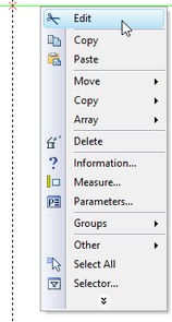
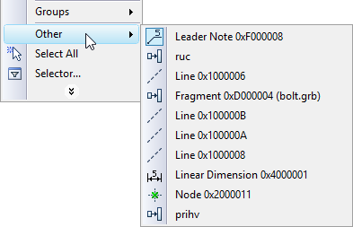
The context menu of an element can be accessed by right-clicking ![]() on the element. The menu contains items for editing, deleting, moving and copying the element, as well as changing its properties by calling the parameters dialog box. One can also view the information about the selected element, measure it, and change the selector settings. When working with complex drawings, several elements might be near the cursor.
on the element. The menu contains items for editing, deleting, moving and copying the element, as well as changing its properties by calling the parameters dialog box. One can also view the information about the selected element, measure it, and change the selector settings. When working with complex drawings, several elements might be near the cursor.
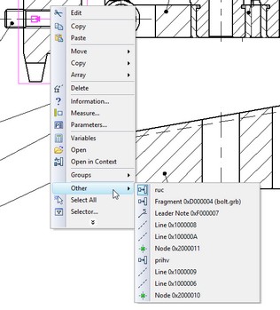
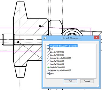
To select the desired element in this situation, use the "Other…" item in the context menu for selecting the element from list. The list contains the elements nearest to the cursor. Only the elements allowed by the selector settings are included in the list. The number of the nearby elements in the list can be set in the selector settings dialog box. This dialog also provides the options for the list representation. The latter can appear as a context menu or as a resizable dialog box floating on screen, providing the user better view of the drawing elements.
A group of elements can be selected in the command-waiting mode as well. Just like in the case of the editing commands, various methods can be used for the group selection: selecting by box left to right (selected are all elements that are fully within the specified region); selecting by box right to left (selected are all elements that at least partially enter the specified region); a serial selection of elements using <Shift>+![]() , <Ctrl>+
, <Ctrl>+![]() . The context menu will contain the commands for moving/copying, deleting and modifying properties of the selected elements.
. The context menu will contain the commands for moving/copying, deleting and modifying properties of the selected elements.
Changing various type element parameters outside any command
Use the properties window to simultaneously change parameters of multiple elements while in the command-waiting mode. In this way, unlike using the specific element editing commands, one can change parameters of various type elements simultaneously.
While in the command-waiting mode, the property window contains a dialog box for changing parameters of the selected element. The dialog is inactive by default. To activate the dialog, enter the properties window and expand the group Parameters. After that, upon selecting any element, the element parameters will be displayed in their property window. To open the dialog box automatically, select elements and call the Parameters command in the context menu.
To turn off the active mode of the dialog, close the “Parameters” group.
Note: upon single element selection, the Parameters command call from the context menu will open the parameters dialog box for the given element.
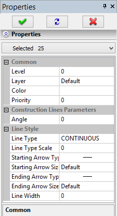
The properties dialog box for the selected elements consists of two parts. The main part is "Properties", and the auxiliary one is "Property Sets". The main part contains the property table for the elements being edited. By default, all selected elements are subject to editing. The box "Selected" in the upper part of the dialog box displays the number of the selected elements. The list of elements to be edited can be limited to elements of one type by selecting the type in the pull-down list off the mentioned box. In this case, the table will contain only the properties of the selected type elements. The entered changes will also affect the elements of this type only rather than the whole selected group.


By default, the table displays all properties of the elements being edited. Checking the "Only Common" box limits the table contents to the common properties only. To change properties of the elements, check the desired properties in the table, enter the required values in the cells on the right-hand side, and press the ![]() or
or ![]() button in the upper part of the dialog box. Upon picking the
button in the upper part of the dialog box. Upon picking the ![]() ("End edit") button, the entered changes are applied to the selected elements. The element processing ends and the elements get de-selected at this point.
("End edit") button, the entered changes are applied to the selected elements. The element processing ends and the elements get de-selected at this point.
The ![]() ("Apply Changes") button applies the entered changes to the elements as well. However, element processing continues in this case. This button is handy in the cases when various parameters are to be assigned to different element groups within the selected set.
("Apply Changes") button applies the entered changes to the elements as well. However, element processing continues in this case. This button is handy in the cases when various parameters are to be assigned to different element groups within the selected set.
The ![]() ("Cancel edit") button can be used to abandon the entered changes and finish processing the selected set of elements. Abandoning changes and finishing the selected element set processing can also be done by simply clicking
("Cancel edit") button can be used to abandon the entered changes and finish processing the selected set of elements. Abandoning changes and finishing the selected element set processing can also be done by simply clicking ![]() within the drawing area.
within the drawing area.
An additional button [From Element] allows selecting an element on screen whose properties will be used as current properties of the edited elements. To use this option, first select the properties in the table whose values are to be taken from the element. Then press the button and select with ![]() the desired element on the screen. The parameter values will assume those of the selected element.
the desired element on the screen. The parameter values will assume those of the selected element.
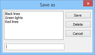
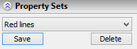
An auxiliary part of the dialog box, the "Property Sets", allows to save the current set of properties under a specific name for their later reuse. To save the composed combination of parameters as a set of properties, press the [Save] button. A "Save as" dialog box will come up on screen for specifying the name of the new set. All existing named property sets are listed in a box in the upper part of the dialog box. A set can be deleted from the list by selecting with ![]() and pressing the [Delete] button. The name of the set to be saved is entered in a box in the bottom part of the dialog box. Upon entering the name, press the [Save] button. The "Save as" dialog box will close, and the saved set name will appear in the pull-down list. The [Cancel] button closes the window without saving the new set. To load a saved set, simply select it in the pull-down list of sets.
and pressing the [Delete] button. The name of the set to be saved is entered in a box in the bottom part of the dialog box. Upon entering the name, press the [Save] button. The "Save as" dialog box will close, and the saved set name will appear in the pull-down list. The [Cancel] button closes the window without saving the new set. To load a saved set, simply select it in the pull-down list of sets.
Copying element properties through clipboard
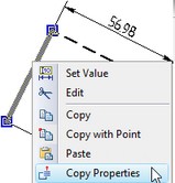
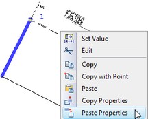
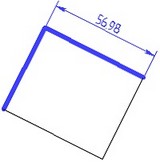
In the context menu for any 2D element the command “Copy Properties” is available. When this command is called, parameters of the selected element are copied into the internal clipboard. After that, upon selecting any other 2D elements the command “Paste Properties” will be available in the context menu. When this command is called the parameters copied into the clipboard will be applied to selected elements.
|
|
|
Limiting Element Selection. Using Selector and Filter
When working with a dense drawing, it is often difficult to select the desired element on the screen. In this case, it may be necessary to limit the list of the elements available for selection. This can be done in several ways. Some of them, such as using the level and layer mechanisms, were already mentioned in capter "Brief Introductory Course". However, these mechanisms either modify the drawing, or allow to temporarily hide construction elements only.
The most general and convenient way that does not require drawing modifications is using the selector and the filter. These tools perform similar functions of limiting selection, however, the selector does this based on element types, while the filter – on the element parameters. Besides, changing selector settings is only available in command-waiting mode, while the filter works in transparent mode. The latter means, the filter settings can be modified at any time, without quitting the current command. The selector and filter settings work independently, adding to each other's function. The elements, whose selection is disallowed by either the selector or the filter, can't be selected on the drawing neither by ![]() , nor via the creation and editing command options described above.
, nor via the creation and editing command options described above.
Selector
The selector settings are managed by the command "FT: Set Selector Configuration". This command can be called only in the command-waiting mode from the toolbar or the textual menu as follows:
Icon |
Ribbon |
|---|---|
|
|
Keyboard |
Textual Menu |
<FT> |
Edit > Selector |
Upon calling the command, the selector configuration dialog box comes up on screen. The main field of this dialog, "Select Elements of Types", contains the list of all system element types. The elements allowed for selection are checkmarked at the left of their type names. By default, all elements are allowed for selection. To disallow selection, un-check the respective type with the ![]() click. The buttons
click. The buttons ![]() ,
, ![]() and
and ![]() help quickly set, clear and invert checkmarking of the element types.
help quickly set, clear and invert checkmarking of the element types.
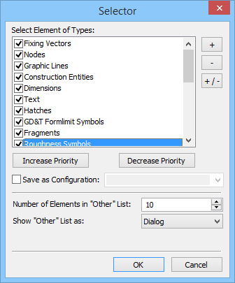
A specified combination of settings can be saved as a named selector configuration. To do so, check the "Save as Configuration" item and enter the name for the new configuration in the box on the right-hand side. Additional items in the selector configuration dialog box, such as "Number of Elements in 'Other' List" and "Show 'Other' List as", allow setting different modes of the list display. The list comes up for a selected element upon calling the "Other" command in the context menu. The effect of these settings was described above, in the "Selecting elements outside any command" topic.
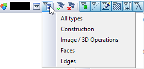
Pressing the [OK] button saves the defined settings and closes the command. The [Cancel] button closes the dialog box without saving changes. The selector can later be quickly set up based on a saved configuration. This is done using the ![]() button on the system toolbar. Pressing this button brings up a pull-down list containing all available selector configurations. Selecting a configuration in the list automatically sets up the selector per the configuration parameters.
button on the system toolbar. Pressing this button brings up a pull-down list containing all available selector configurations. Selecting a configuration in the list automatically sets up the selector per the configuration parameters.
There are several additional buttons on the system toolbar for controlling and quick adjustment of the selector settings. The ![]() and
and ![]() buttons are used to quickly allow/disallow selection of all types of elements.
buttons are used to quickly allow/disallow selection of all types of elements.
The buttons with various element type symbols, such asthe ![]() ,
, ![]() ,
, ![]() ,
, ![]() ,
, ![]() ,
, ![]() ,
, ![]() ,
, ![]() and
and ![]() buttons in the 2D window, other in the 3D window, define the current set of the elements allowed for selection. The "pushed" icons correspond to the element types allowed for selection. Besides, one can quickly allow/disallow selection of the respective element types by pressing these buttons. Pressing any of these buttons toggles its setting to opposite. This allows or disallows selection of the respective element type in the selector settings. Pressing any of these buttons while holding the <Ctrl> key down, turns on selection of exclusively the given element type. Selection of other element types simultaneously turns off.
buttons in the 2D window, other in the 3D window, define the current set of the elements allowed for selection. The "pushed" icons correspond to the element types allowed for selection. Besides, one can quickly allow/disallow selection of the respective element types by pressing these buttons. Pressing any of these buttons toggles its setting to opposite. This allows or disallows selection of the respective element type in the selector settings. Pressing any of these buttons while holding the <Ctrl> key down, turns on selection of exclusively the given element type. Selection of other element types simultaneously turns off.
The same result can be achieved by double clicking ![]()
![]() the required button.
the required button.
Filter
Filter parameters can be set or modified either in the command-waiting mode or in the transparent mode within any command. Call the command using:
Icon |
Ribbon |
|---|---|
|
|
Keyboard |
Textual Menu |
<FL> |
Edit > Filter |
Managing the filter involves setting one or more conditions on the parameters of the objects to be selected. The elements are disallowed for selection whose parameters do not satisfy any of the filter conditions. This is so even for elements allowed for selection by the selector.
Calling the command brings up the filter parameters dialog box.
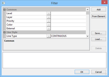
The current filter parameters, which are the currently active condition set, are displayed in the lower part of the dialog. This set consists of one or several conditions joined by Boolean "OR" operator. Thus, an element is allowed for selection if at least one of the conditions is satisfied among the current set.
Each condition in a set is written out on a separate line. It consists of limitations on the element parameter values. The limitations are joined in a condition by Boolean "AND" operator. To satisfy a condition, the element must comply with all and any of the limitations thereof.
To create a condition, use the main pane of the filter dialog box. This is a table of properties of all elements in the current document.
To define a limitation on the value of some parameter you need to select the parameter in the table and to press ![]() button in the middle column. The drop-down list will appear. Here you can select limitation type of the parameter value: Equal, Not Equal, Greater, Less.
button in the middle column. The drop-down list will appear. Here you can select limitation type of the parameter value: Equal, Not Equal, Greater, Less.

The parameter value for the selected limitation is specified in the right column. Numeric and text values are specified manually. If in the system there are values lists for a parameter, you can select a value from the drop-down list. The drop-down list appears automatically when you press ![]() on the field.
on the field.

Once all limitations are defined, press the [Add] button. The just created condition will appear in the lower pane of the dialog box. If there was already a set of conditions at the time of the new condition creation, the latter becomes part of this set.
When creating a condition, the parameter values can be read from a specific element. To do so, checkmark the necessary properties, and then press the [From Element] button. The dialog box will temporarily disappear from screen, making possible selection of the desired element in the drawing window using ![]() . Once an element is selected, the filter parameters dialog box comes back on screen. The checked parameter values will be the same as those of the selected element.
. Once an element is selected, the filter parameters dialog box comes back on screen. The checked parameter values will be the same as those of the selected element.
To delete the current condition set or a part thereof, use the [Delete] button. To do so, first highlight with ![]() one or several conditions. Then press [Delete], and those will be deleted.
one or several conditions. Then press [Delete], and those will be deleted.
The specified set takes effect after closing the filter dialog. Only the elements satisfying the current filter settings will be available for selection in any mode of T-FLEX CAD system.
Element search
Sometimes, the system might fail to calculate location of some element during regeneration. In such a situation, the system will display an appropriate message with the Id of this element. To find this element on the drawing, one can use the command "FD: Find Element":
Icon |
Ribbon |
|---|---|
|
Edit → Additional → Find |
Keyboard |
Textual Menu |
<FD> |
Edit > Find |
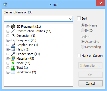
Upon calling the command a dialog box comes up on screen for searching a 2D or a 3D element. An element can be searched by either of the two ways as follows. One way is to use the input box in the upper part of the dialog. Enter the Id or the name of the searched element. If such element is found, the buttons in the right part of the dialog box will become accessible. Meanwhile, the element may be marked on the screen, depending on the "Mark on screen" attribute. Pressing the [OK] button closes the dialog window, while highlighting (selecting) the found element on the screen. Pressing the [Information] button opens the element information window. If the element is not found, the buttons remain inaccessible.
A pull-down list of the input box in the upper part contains the previous queries. An Id or name can be selected from this list if desired.
Another way of searching for an element is using the tree in the main pane of the dialog box that contains all model elements. When an element is selected in the tree, the upper input box displays its Id or name. The buttons in the right part of the dialog become accessible as well.
An additional "Sort" flag serves to sort elements in the tree by the name or by the ID in the desired order (ascending or descending).
The search command can be called in transparent mode from within any other command. In this case, the total list will only contain the elements that are allowed for selection in the current command.
Moving, copying, transforming elements. Working with clipboard
New drawing elements can be created using already existing ones. For this purpose, use the general move/copy command. It was described in the chapter "Moving and copying elements. Working with clipboard". This command can be called either from the textual menu and keyboard, or from the context menu for the elements to be transformed.
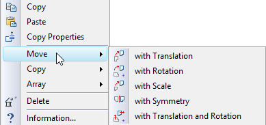
To call the command from the context menu, select the necessary drawing elements and right-click ![]() . The context menu will be containing commands by groups for calling various modes of the move/copy command, specifically, "Move", "Copy", "Array". The modes under the "Move" group allow changing location and size of the selected elements. Besides, an option is provided for moving all related elements. For example, moving some construction element will be affecting the placement of all related elements to this one, either the construction or the graphic ones.
. The context menu will be containing commands by groups for calling various modes of the move/copy command, specifically, "Move", "Copy", "Array". The modes under the "Move" group allow changing location and size of the selected elements. Besides, an option is provided for moving all related elements. For example, moving some construction element will be affecting the placement of all related elements to this one, either the construction or the graphic ones.
Meanwhile, all parametric dependencies between elements will stay intact.
The "Copy" group provides the modes for creating a copy of the selected elements (as well as all related ones) at any location of the current document. The created copies can be made associatively related to the original objects, or become independent elements.
The linear and circular array creation modes are provided under the "Array" group. Similar to simple copying, the created result can be either an array with associative relation to the original objects, or a set of independent elements.
T-FLEX CAD also works with the clipboard. Clipboard commands can also be called either from the textual menu, or using the context menu for the selected elements ("Copy", "Copy with Point", "Paste", "Paste Special…"). Thus selected elements can be copied into another T-FLEX CAD document or into an external application. One can also insert a picture or text from an external application into a T-FLEX CAD drawing.
Undoing user actions
Errors inavoidably occur when working with any system, especially while learning. Correcting errors takes time. T-FLEX CAD system helps simplify this process. A certain number of latest user actions are remembered by the system. The length of the undo and redo buffers is set in the command "SO: Set System Options", on the Performance tab, in the Undo/Redo buffers box.
The user actions remembered by the system can be undone by a certain number of steps back. This can be done by repeatedly calling the command "UN: Undo Changes", that brings the system back by one step. The "UN: Undo Changes" command can be called from any other command using <Alt><BackSpace> or <Ctrl><Z> combination.
If the command "UN: Undo changes" was called in error, there is the "RED: Redo Changes" command in the system, which restores the undone action. The "RED: Redo Changes" command can be called from any other command by <Ctrl><BackSpace> or <Ctrl><Y> combination. Repeatedly calling the command "RED: Redo Changes" brings the system into the state when undoing began.
The "UN: Undo Changes" command can be called as follows:
Icon |
Ribbon |
|---|---|
|
|
Keyboard |
Textual Menu |
<UN>, <Ctrl><Z>, <Alt><BackSpace> |
Edit > Undo |
The "RED: Redo Changes" command is called via:
Icon |
Ribbon |
|---|---|
|
|
Keyboard |
Textual Menu |
<RED>, <Ctrl><BackSpace> |
Edit > Redo |
To cancel or repeat several actions at once, press the button ![]() on the main toolbar to the right of the icon of the corresponding command. After pressing the button the dropping list of actions which can be canceled or repeated will pop up. Then it is enough just to select the desired group of actions with the help of
on the main toolbar to the right of the icon of the corresponding command. After pressing the button the dropping list of actions which can be canceled or repeated will pop up. Then it is enough just to select the desired group of actions with the help of ![]() .
.
General principles of assigning parameters. Assigning variables to parameters
General principles of assigning parameters
Various ways of assigning parameter values are used in element creation and editing commands. These include using parameter dialog box and property window, as follows:
● A parameter can be assigned a constant value. For example, the parameter "Rotation angle" of a text can be assigned 0.
● A parameter value can be substituted by the string "Default". This means, the parameter value will be set from the respective parameter of the command "ST: Document Parameters". For example, the parameters on the "Font" tab in the parameter dialog box for dimensions, roughnesses and notes will be substituted from the "Font" tab of the command "ST: Document Parameters" when the respective elements are displayed.
Using default parameters helps quickly modify elements of the whole drawing. For example, using default parameters for dimensions allows to instantly change dimension display and, therefore, the whole drawing. This can be done by modifying parameters on the "Dimensions" tab of the "ST: Document Parameters" command.
● The values of most of various element parameters defined by number can be set using string variables and expressions. In this case, the parameter value will be driven by the value of the variable or expression. In this way, the value of the parameter can be changed by varying the respective variable value. This mechanism allows changing any parameters of the following T-FLEX CAD elements: the size of text boxes, the slanting angle, the size of arrows of the dimension leaders and graphic lines, etc. You can use variables to define drawing parameters that are defined in the "ST: Document Parameters" command, such as scale, paper size, font size, etc. Variables can also be used for defining the system visibility levels of the elements set in the command "SH: Set Levels".
Assigning variables to parameters
● When assigning a variable to a numeric parameter, enter the variable name or expression without any special symbols. Examples: A or A+B
● When assigning a variable to a string parameter, enter the variable name or expression in braces. Examples: {$NAME} or {A+B}
● When assigning string parameters in braces one can enter either the real variables or textual variables.
If a new variable name was entered when assigning a parameter, the value of this variable must be set after leaving the menu.
When a variable is introduced, the format of its value representation can be specified along. Use the following syntax for typing variable values:
{<variable name>} or {<format>,<variable name>}
The following example demonstrates use of formatted variable representation.
Today {"%lg",DAY}, {"%s",$MONTH}, {YEAR}
Note that the textual variable $MONTH begins with the '$' character, as this is the prefix for all textual variables.
The format structure, used for the T-FLEX variables, follows the syntax of the input/output formats in "C" programming language.
Using formats will help you control the appearance of the variable value on screen. For example, formats can control the number of displayed decimal digits or justification of the displayed value.
Context menu for dialog input boxes
When working with dialog boxes, an additional set of commands is available in context menus. A context menu can be called by placing cursor within an input box of the dialog and right-clicking ![]() :
:
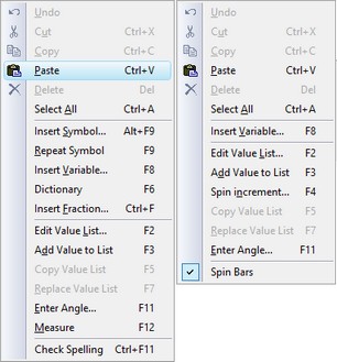
Undo. Undoes the last change.
Cut <Ctrl+X>. Cuts selected text to clipboard.
Copy <Ctrl+C>. Copies selected text to clipboard.
Paste <Ctrl+V>. Pastes text from clipboard.
Delete <Del>. Deletes selected text.
Select All <Ctrl+A>. Selects all text in the current input box.
Insert Symbol… <Alt+F9>. Inserts a symbol from a special symbol table. The symbol code is actually entered in the input box instead of the symbol itself, for example, %%066 for the diameter symbol. This may be used for entering symbols in some textual input boxes. The data from these boxes will be inserted in the drawing (see the section "Paragraph text" of the "Text" chapter).
Repeat Symbol <F9>. Inserts last symbol again.
Insert Variable… <F8>. Inserts an existing variable from list. The variable name is inserted in the input box in braces. The drawing will display the actual value of the variable. The variable values can be changed in the variable editor or, in some cases, directly on the drawing (see "Paragraph text" of the "Text" chapter).
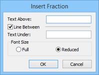
Insert Fraction… <Ctrl+F>. Inserting the fraction into the dialog box. Can be used, for instance, for assigning the content of text fields in dimensions, leader notes, text, etc. Upon calling the command the window of an auxiliary dialog is displayed for setting the parameters of the fraction. |
|
Dictionary <F6>. Inserts text from dictionary. For detailed information, see "Working with dictionary" of the "Text" chapter.
Edit Value List… <F2>. Value lists can be created for the dialog input boxes. The lists are preset for some boxes, for example, the input boxes "Datum" and "Value" in the "GD&T Symbol Parameters" dialog box. The command brings up a window for editing the values list. The list can be divided into columns. Entries in a column can be grouped between horizontal dividers.
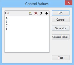
Insert Value to List <F3>. This command adds the current value from the dialog input box into the list. If the list did not exist, it will be created.
Copy Value List <F5>. This command copies the list of values of the given dialog field into the clipboard.
Replace Value List <F6>. This command replaces the list of values assigned to the given dialog field by the list of values from the clipboard. The list must be copied to the clipboard in advance using the command "Copy Value List".
Spin Bars. This command enables the stepper – the way to modify the parameter in the respective field using the mouse wheel or the button ![]() .
.
Spin increment… <F4>. You can define the parameter value increment of the stepper. One of the three settings can be chosen in the spin increment control dialog box: "Default", "Value", "By Value List".
Value. Set a numeric value of the increment.
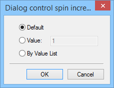
By Value List. Setting this option will allow to scroll through the list of values in the case the list was created for this input box of the dialog.
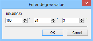
Enter Angle… <F11>. This command allows converting an angle value to the decimal format. The command brings up a dialog box. The respective input boxes of the dialog allow entering an angle value in degrees, minutes and seconds. This value will be converted into the decimal format.
Measure. <F12>. This command allows reading geometric data from existing drawing elements and using it for creating new elements. Parametric dependencies can also be introduced between the elements. For more information, see the chapter "Measuring elements and relations between them".
Check Spelling. <Ctrl+F11>. Checking the spelling of the content of the dialog field, for which the context menu has been called.