Inserting Fragments into a Drawing |
  
|
Inserting Fragments into a Drawing |
|
There are several ways of inserting a fragment into an assembly drawing:
1. By using the command "FR: Create Fragment".
2. Within the "Library Explorer" or library window.
3. By creating a fragment directly in the assembly context.
The following description relates to the first two techniques of inserting a fragment into a drawing. The third technique is described in the dedicated section "«Top-Down» Design".
To insert a fragment into an assembly drawing, call the command "FR: Create Fragment":
The following options will appear in the automenu:
![]() <O> Select File
<O> Select File
![]() <C> Create new Fragment in Assembly Context
<C> Create new Fragment in Assembly Context
![]() <G> Mark out Fragment
<G> Mark out Fragment
![]() <P> Set Fragment parameters
<P> Set Fragment parameters
![]() <R> Repeat previous Fragment (accessible upon a repeated call to the command)
<R> Repeat previous Fragment (accessible upon a repeated call to the command)
![]() <F> Select Fragment to create its copy
<F> Select Fragment to create its copy
![]() <F4> Execute Edit Fragment command
<F4> Execute Edit Fragment command
![]() <Esc> Exit command
<Esc> Exit command
The controls for customizing parameters of the fragment will appear in the properties window. They are put into several sections, their number and structure depend on the fragment creation approach. The sections of the properties window allow selecting the file of the fragment being inserted, a way of attaching the fragment, specifying external variables of the fragment, etc.
Before selecting the fragment file the dialog in the properties window contains only three sections: “Basic parameters”, “Fragment parameters”, “Options”. The values of the parameters, defined in the properties window before file selection, are automatically stored as default values for all subsequently inserted fragments.
The first step when inserting the fragment is the selection of the file of a fragment. The dialog window for selecting a file can be called with the help of the option ![]() or by pressing the button
or by pressing the button ![]() in the section “Basic parameters” of the command's properties window. In the window for file selection it is necessary to indicate the document file of the fragment. After selecting the file, a dynamic image of the inserted fragment attached to the cursor will appear in the drawing window. The contents of the automenu will be changed. The new state of the automenu will depend on the fragment attachment approach specified in the properties window: by fixing points or by fixing vector.
in the section “Basic parameters” of the command's properties window. In the window for file selection it is necessary to indicate the document file of the fragment. After selecting the file, a dynamic image of the inserted fragment attached to the cursor will appear in the drawing window. The contents of the automenu will be changed. The new state of the automenu will depend on the fragment attachment approach specified in the properties window: by fixing points or by fixing vector.
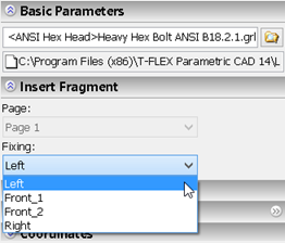
The fragment attachment approach is specified in the section “Insert Fragment”, with the help of the parameter “Fixing”. In case the fragment is attached by the fixing vector, the required fixing vector can be chosen from the drop down list of this parameter. The required page of the fragment document can be selected here as well (in case of multi-page document).
In the section “Fragment parameters” of the command dialog it is possible to specify various settings for fragment insertion. A detailed description of these parameters is presented in the section “Fragment parameters”.
The values of the fragment external variables are specified in the section “Variables” of the properties window. This section is present in the dialog of the command's properties window if the fragment being inserted has external variables.
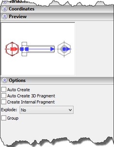
In the section “Preview” of the command dialog the inserted fragment is dynamically displayed in accordance with the specified values of the external variables, fixing elements (fixing points and fixing vectors) are indicated.
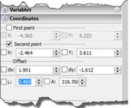
When defining fragment insertion parameters, you need to specify the placement points of the fixing vector or fixing point in the drawing area (see the section “Defining Fragment Placement in the Assembly Drawing”). The coordinates of the specified points are shown in the section “Coordinates” of the command's properties window.
After attaching the fragment on the current drawing, it is necessary to finish creating the fragment by pressing ![]() in the automenu or in the command's properties window. Before that a series of additional operations can be performed with the help of the options appearing in the automenu of the command at this stage of the fragment insertion:
in the automenu or in the command's properties window. Before that a series of additional operations can be performed with the help of the options appearing in the automenu of the command at this stage of the fragment insertion:
![]() <K> Input Fragment insertion points
<K> Input Fragment insertion points
![]() <P> Set Fragment Parameters
<P> Set Fragment Parameters
![]() <Y> Create Name for selected Element
<Y> Create Name for selected Element
![]() <Ctrl+O> Open Part
<Ctrl+O> Open Part
![]() <O> Open Fragment in Context of Assembly
<O> Open Fragment in Context of Assembly
![]() <X> Automatic Explode
<X> Automatic Explode
![]() <Ctrl+X> Explode with Constructions
<Ctrl+X> Explode with Constructions
![]() <F4> Open Fragment file for editing
<F4> Open Fragment file for editing
![]() <C> Select Clipping Hatch
<C> Select Clipping Hatch
![]() <I> Select Other Element
<I> Select Other Element
![]() <Esc> Deselect all elements
<Esc> Deselect all elements
The option ![]() starts the mode of respecifying the fixing point of the fragment.
starts the mode of respecifying the fixing point of the fragment.
The option ![]() allows assigning the name for the inserted fragment. The fragment name can be used, for example, for search, for automatic creation of nodes of the fragment in the assembly, for obtaining the values of the fragment variables in the assembly drawing with the help of the function get:
allows assigning the name for the inserted fragment. The fragment name can be used, for example, for search, for automatic creation of nodes of the fragment in the assembly, for obtaining the values of the fragment variables in the assembly drawing with the help of the function get:
get («Fragment name»,« Variable name»),
where «Fragment name» – the name that was specified for the fragment, and «Variable name» - the name of the variable from the fragment drawing the value of which has to be obtained in the assembly drawing.
To explode the fragment automatically the options ![]() and
and ![]() are used (see the section “Exploding Fragments” in the chapter “Basic Fundamentals and Concepts of Working with Assemblies”). The options
are used (see the section “Exploding Fragments” in the chapter “Basic Fundamentals and Concepts of Working with Assemblies”). The options ![]() and
and ![]() allow opening the file of the inserted fragment straightway for editing, after its creation has been finished automatically.
allow opening the file of the inserted fragment straightway for editing, after its creation has been finished automatically.
If necessary, for example, for fast insertion of several fragments in a row, it is possible, by setting on the flag “Auto Create” in the section “Options” of the command's properties window, to turn on the mode of finishing fragment insertion automatically after specifying its fixing points. In this case, the fragment insertion will be finished automatically right away after specifying all fragment fixing points or its fixing vector.
Detailed description of all steps of inserting a fragment (selecting the fragment file, defining external variable values and placement, attachment of the fragment to the assembly drawing) can be found in the respective topics of this section.
If you need to insert another instance of one of already inserted fragments, you can conveniently use the options ![]() and
and ![]() (described below, in the topic “Repetitive fragment insertion”).
(described below, in the topic “Repetitive fragment insertion”).
Selecting fragment file
For specifying the fragment file the standard window for file selection is used. It appears after using the option:
![]() <O> Select File
<O> Select File
Both your directory structure and the installed T-FLEX CAD libraries can be the source for this selection. Switching between these two sources is carried out with the help of drop down list found at the upper left corner of the file selection window.
When you are in the fragment insertion command, it is also possible to indicate the library element in the service window “Library Explorer”.
Selecting fragment from library
If a library element is used as a fragment, it can be assembled directly in the "Library Explorer" window or in the auxiliary library window (see the chapter "Libraries"), bypassing a direct call to the command "FR: Create Fragment". In this approach, you can use the context menu commands or the Drag&Drop mechanism. To use the latter, select a fragment in the "Library Explorer" or library window by pressing ![]() on the fragment and drag it into the drawing area, while holding the left mouse button down. This will automatically activate the command "FR: Create Fragment". You can get the same result by right-clicking
on the fragment and drag it into the drawing area, while holding the left mouse button down. This will automatically activate the command "FR: Create Fragment". You can get the same result by right-clicking ![]() over a fragment in the "Library Explorer" or library window, and then selecting the context menu item "Insert".
over a fragment in the "Library Explorer" or library window, and then selecting the context menu item "Insert".
Defining fragment external variables
If external variables exist in a drawing, you will be asked to define the values when inserting this drawing as a fragment into assemblies. When attaching to the connector, necessary values can be specified automatically.
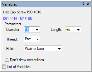
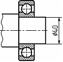
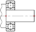
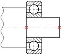
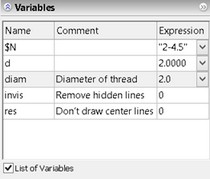
Let's review defining fragment external variables in the example of a ball bearing drawing that we will be inserting into a shaft drawing. An external variable "d" is created in the ball bearing drawing that drives its inner diameter.
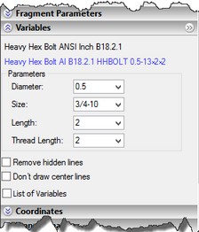
After choosing the name of the fragment-bearing, in the command's properties window the tab “Variables” will appear which allows specifying the values for the fragment external variables. The standard list of variables or user-defined dialog with the control elements can be used for specifying the values (see the chapter "Control elements").
If the fragment drawing has text fields with an external variable inserted into them (for example, title block), then the values of such variables can be changed directly on the assembly drawing.
Let's consider first defining the fragment external variables using the list of variables. In this way, variables may be assigned data of three types: 1) Constant (a number in the case of a real variable, or a string in the case of a text variable); 2) An assembly variable; 3) None (the variable entry left blank). |
|
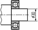
Type 1: Assigning constant value
Let's set a particular value of the ball bearing diameter, for example, "30". |
|
In this case, as the shaft diameter varies, the inner diameter of the ball bearing will not change. To modify the value of the ball bearing external variable, you will have to edit the fragment. |
|
Fragment external variables can be pre-defined with default values when offered for defining. The default values are copied from the respective variables in the original fragment drawing file, if the flag "Substitute Variable values" is set in the command "SO: Set System Options" on the tab "Fragments".
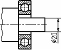
Type 2: Assigning assembly variable
Instead of a fixed value of the ball bearing external variable, let's type in the name "Diameter" of an existing assembly variable. If a user puts in the name of a non-existing variable, the system will prompt a user to create a new variable. |
|
Suppose, at the insertion time, the variable "Diameter" equals "20". Let's modify the variable "Diameter" to "40". In this case, the ball bearing image will adjust automatically. An assembly variable can be selected from the list of existing variables by pressing the key <F8> (see the chapter "Setting Common Parameters of System Elements") |
|
If a fragment external variable was named after an assembly variable, and such assembly variable actually exists in the current assembly drawing, the latter value will be automatically assigned to the fragment variable (see the chapter "Variables").
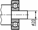
Type 3: Undefined value
![]()
You can skip defining the external variable altogether, leaving the entry blank.
In this case the value read from the fragment file will be put into. To change now the ball bearing diameter, it is necessary to download its file as a separate drawing, specify the desired diameter value in that file, and after saving the file return to the assembly drawing. This scheme is used in practice rarely, when it is required to modify the assembly drawing by changing the values of the variables in the fragment file.
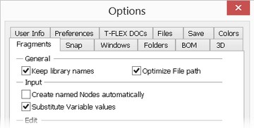
For filling in unspecified values of the variables automatically, in the System options a special parameter «For filling in unspecified values of the variables automatically, in the System options a special parameter «Substitute variable values» is turned on by default. In this case, upon inserting the fragment, all variables automatically get constant value read from the fragment.» is turned on by default. In this case, upon inserting the fragment, all variables automatically get constant value read from the fragment.
Working with user-defined dialog
User-defined dialog with control elements represents itself a more visual tool for working with external variables of the fragment. The set of different control elements allows specifying the values for the variables with the help of various toggles, buttons and also by entering the values from the keyboard or working with the list of values. There are two regimes in which the dialog fields for the value entry can operate. Either the value of the variables or the expressions themselves can be displayed in the fields of the dialog. In the latter case, the values of the expressions are shown to the right of the entry field. The second regime works in case the parameter «Show expressions» has been set on in the properties of the entry field. Details of creating user-defined dialogs are described in the chapter “Control Elements. Creating User Defined Dialog Boxes”.
In any case, a user can write both values and expressions into the entry fields. After finishing the data entry (when the focus of input is shifted to another field), the fragment external variable which is related to the given entry field will be set equal to the expression.
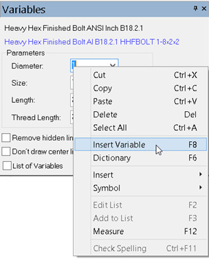
To define a relation between a fragment external variable and an assembly variable, you can use the context menu commands.
You can call the context menu command "Insert Variable" or, instead, simply press <F8>. The standard "Insert Variable" dialog box will be displayed in the screen. Upon selecting an assembly variable, its value will be assigned to the fragment external variable. A checkmark before the respective command of the context menu will be indicating that the current fragment variable has a relation with an assembly variable. Direct editing of the dialog entries will be modifying the respective assembly variable values. To cancel such a relation, call the same context menu command again. To cancel such a relation, call the same context menu command again. When the connection with the variable is established, it is possible to continue working with the drop-down lists of the values. While doing it, the assembly variable connected to the given fragment variable will be assigned the new value from the drop down list. |
|
If necessary, it is possible to switch to the mode of working with the list of variables instead of working with the user-defined dialog. For switching to another regime, use the flag “List of Variables” found at the bottom of the dialog.
For loading one of the saved configurations (predefined set of values for the fragment external variables), use the drop-down list «Configuration:» at the bottom of the user-defined dialog.
The command for working with the configuration can be invoked by the following means:
Icon |
Ribbon |
|---|---|
|
Parameters → Tools → Configurations and variations |
Keyboard |
Textual Menu |
<FCE> |
Parameters > Model Configurations and variations |
Details of the work with the command can be found in the chapter “Model Configurations and variations”.
Working with the connector
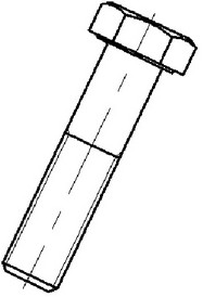
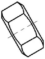
Upon attaching the fragment (for example, a nut) to the connector of another fragment (for example, a bolt) the values of the variables can be obtained automatically. For successful automatic connection of the variables with the connector, the following conditions must be met:
1.In the connector the named values have to be specified. These named values will subsequently serve as a link between the variables of the fragment having a connector (bolt) and the variables of another fragment (nut) which will be attached to the given connector in the assembly.
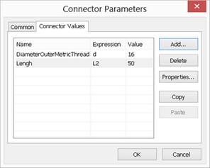
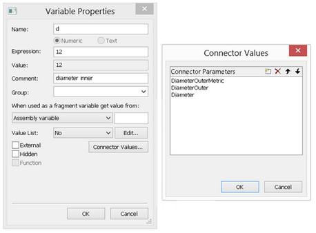
2.For corresponding variable of the fragment the list of names for the values or at least one name of such sort must be specified for linking with the connector. The name of the value for the variable has to be specified in advance in the variables editor in the fragment file by modifying the properties of the variable. The name of the connector value specified for the variable must coincide with the name of the value specified in the connector. Only in this case the automatic connection is possible.
3.Upon inserting the fragment, the connector must be chosen. The variables of the new fragment automatically take the values straightway after the connector selection. The image of the fragment takes the form in accordance with the values of the variables.
The connection between the fragment variables and connector values can be determined manually. To do it, resort to the list of the fragment variables in the command of creating and editing the fragment. If the user-defined dialog is used for controlling the variables, switch to the list of the variables. The manual setup of the connection between the variable and the connector value is needed in case the fragment is attached to the connector but for its variable the connector value name is not designed or that name does not coincide with the value in the connector. In this case, clicking in the field “Connector Values…” will show the list of the connector values and upon selecting one of the values, the connection will be established. The field will be marked by a special symbol.
Using configuration
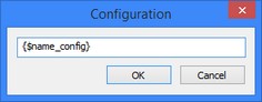
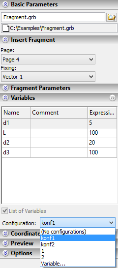
For specifying the values of the fragment’s external variables, it is also possible to use configurations created in the document of the fragment. When configurations exist in the fragment’s document, the parameter “Configuration” is available in the fragment’s parameters dialog. Its drop-down list contains the names of the configurations created in the fragment’s document. When selecting a configuration, all fragment’s external variables are automatically assigned the values stored in the selected configuration. In addition to the names of fragment’s configurations, the list of the parameter “Configuration” contains additional items: No configurations – this option is used to prevent the use of configuration; Variable… – allows specifying the name of the used configuration with help of the variable. After selecting this item in the list, the window for specifying the variable’s name will pop up on the screen. The variable’s name can be specified either manually (in curly brackets) or with the help of the context menu command “Insert Variable… F8”.
|
|
Defining fragment placement in the assembly drawing
When specifying location of the fixing vector or fixing points, the nodes of the assembly drawing can be picked for carrying out fragment attachment to the elements of the assembly drawing. When changing location of the specified nodes of the assembly drawing, the fragment placement will be modified as well. |
|
|
If necessary, the fragment can be inserted by specifying the absolute coordinates for the fixing vector and points. This becomes possible upon clicking at the desired place of the drawing in the absence of object snap. The object snap can be turned off via the toolbar «View» or by pressing the key <Ctrl> at the time of the click. In this case, with the help of the section «Coordinates» in the fragment properties window the adjustment of the coordinates of the fragment insertion can be performed.
Fragment placement using fixing vectors
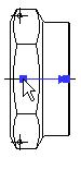
When inserting a fragment by the fixing vector, the system asks to define the vector fixing points.
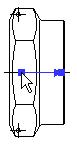
If the fixing vector was defined in the fragment drawing by a single point, then you need to specify only one point in the assembly drawing to place the fragment. Once that is done, the image of the fragment will be placed in this point. The fragment image cannot be rotated in this case. If the fixing vector was defined by two points in the fragment drawing, then the fragment can be placed in several ways. The first way implies specifying two points, the first defining the location of the fragment image, and the second - rotation of the fragment image about the first point. |
|
The option for handling this way appears upon specifying the first point:
![]() <M> Fixing using two points
<M> Fixing using two points
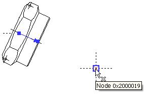
When proceeding in this way and snapping the vector start to one node and the vector end to another, modifying the position of the first node will change the location of the fragment image, while the second one - the orientation.
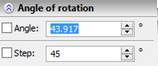
The second approach differs from the first one as follows. The first point still defines the location of the fragment image, while the second point, instead of maintaining the rotation, sets just once the rotation angle of the fragment image with respect to the X-axis of the assembly drawing. The angle of rotation for the fixing vector can be specified as a variable.
This way is handled by the option that appears upon defining the first point:
![]() <M> Fixing using one point and angle
<M> Fixing using one point and angle
With this type of placement, modifications in the position of the first placement node will cause change in the fragment location only, not affecting the rotation angle of the fragment image.
Before confirming the fragment insertion or in the fragment editing command, already inserted points of the fixing vector can be easily changed. For modifying location of the desired point, bring a cursor to this point. The cursor will take the form corresponding to the point number (1 or 2). Next by pressing |
|
The fragment being inserted can have several fixing vectors. For selecting the desired vector, the section “Insert Fragment” in the properties window should be used. In the drop down list «Page» it is possible to select the desired page of the fragment document (if the fragment contains several pages), and then for the selected page the fixing vector is picked in the drop down list “Fixing”. The section “Preview” of the properties window can be also used for changing the fixing vector. Here, on the preliminary image of the fragment, the active fixing vector is highlighted with a red color, the rest are blue. The fixing vector can be selected by clicking in the preview window. |
|
Attaching to connector
When inserting a fragment with a fixing vector, turn on the mode of snapping to connectors. This mode is activated by the automenu option:
![]() <С> Mode of snapping to Connectors
<С> Mode of snapping to Connectors
The option appears in the automenu immediately after selecting a fragment file, if the system determines that the current fragment is placed using a fixing vector. In this mode, as the pointer approaches a connector or a graphic line referenced by the connector, the variables of the fragment being inserted automatically assume the values from the same-name connector variables. This reflects on the changing shape of the fragment. At the same time, the updated fragment automatically snaps to the connector.
When attaching to the connector the system may require specifying additional transformations (see below).
If you need to define the values of other variables, this can be done in a conventional way.
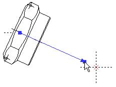
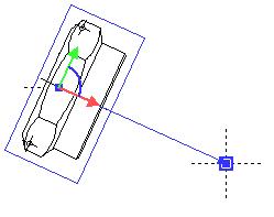
Additional transformations
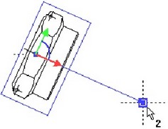
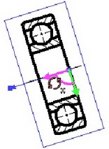
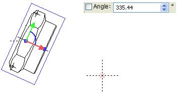
When attaching the fragment with the help of the fixing vector, sometimes it is required to make the fragment location more precise – move or turn the fragment with respect to the axes of the fixing vector, i.e. define additional transformations. Transition to specifying additional transformation can be carried out straightway after specifying the points of the fixing vector. While doing it, a special dragger in the form of the coordinate system will appear on the fragment image. If the cursor is brought to the elements of the dragger (the coordinate axes and the arc between the axes), it will be taking the form in accordance with the offered transformation – |
|
If at this moment |
|
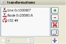
It is possible to define an unlimited number of transformations successively. All specified transformations are put into the properties window. The transformations of similar type (for example, several translations along the same axis) are automatically summed up.
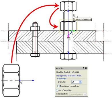
When attaching the fragment to the connectors, the requirement of defining additional transformations can be brought into the fragment file already at the connector creation stage. In this case right away after the connector selection (when attaching another fragment) and reading the values of the variables, the system will automatically turn to specifying the required additional transformation. This approach is frequently used in the libraries of the standard elements since it is not always possible to automatically determine the location of the future fragment. For example, when putting a nut on a bolt, it is almost always necessary to place this nut on the surface being fastened, the attachment to which is specified by a user while defining additional transformations.
Fragment placement using fixing points
If the fragment drawing contains external variables “x1”, “y1”, “x2”, “y2”, etc., then upon inserting the fragment into the assembly drawing you will have to specify as many placement points as you have pairs “x” and “y” with the respective numbers in the fragment drawing.
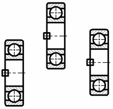
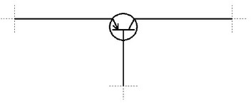
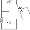
For example, suppose we want to locate the image of the transistor, the drawing of which has three fixing points. Each point specifies location of one transistor contact. When inserting the fragment on the assembly drawing, the system will successively prompt a user to specify location of each point. When specifying the fragment fixing points, the current fixing point number will be drawn next to the cursor. The dynamic image following the cursor helps to evaluate the appearance of the future fragment. If necessary (in case of complicated for dynamic imaging fragments) the dynamic image can be switched off with the help of the option |
|
|
There are two possibilities for specifying locations of the fixing points: attach the fixing point in absolute coordinates (independent of the assembly drawing) or snap to the node on the assembly drawing. Attachment in absolute coordinates is carried out by pressing ![]() while the object snaps are turned off or by pressing simultaneously the key <Ctrl>. Snapping to a node is done via
while the object snaps are turned off or by pressing simultaneously the key <Ctrl>. Snapping to a node is done via ![]() with simultaneous node selection or with the help of the option <N>.
with simultaneous node selection or with the help of the option <N>.
Repetitive fragment insertion
Several options are provided in the fragment creation command "FR: Create Fragment" for repetitive insertion or duplicating fragments. Use of these options speeds up insertion of identical fragments.
Multiple insertions of the last created fragment are supported by the option:
![]() <R> Repeat previous Fragment
<R> Repeat previous Fragment
Selection of a fragment to duplicate in the drawing is done by the option:
![]() <F> Select Fragment to create its copy
<F> Select Fragment to create its copy
Upon calling one of those options, the system asks you to specify just the placement of the fragment in the drawing. In this case, the external variables will have the same values as the fragment being duplicated.
Adding Projections and Schematic Drawings of Models to Assembly Drawing
This option allows us to add projections or schematic drawings of models onto a plane.
|
<W> |
Project 3D fragments onto a workplane |
After the command is activated, the automenu appears.
|
<W> |
Select workplane for specifying projection direction |
|
<F> |
Select 3D fragment |
|
<A> |
Select all 3D fragments in scene |
|
<Esc> |
Exit from the command |
Using the command:
1.Select a plane onto which the model will be projected ![]() . The selected plane will be displayed in the operation’s properties in the «Workplane» column;
. The selected plane will be displayed in the operation’s properties in the «Workplane» column;
2.Select one or several models for projection ![]() or
or ![]() ;
;
3.Select projection type or schematic view.
The source for the 2D fragment being created can be selected in the list in the «Fixing» field:
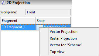
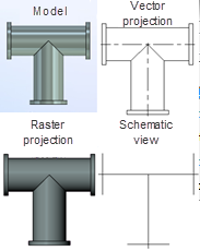
●Vector projection – projection of the selected model is created on the basis of the lines of the model’ image;
●Raster projection – projection of the selected model is created as a 2D fragment;
●Fixing vector – schematic image created earlier is added to the plane. Only those vectors are added to the list which satisfy the workplanes compatibility condition.
Using 2D-fragment as «projection» for 3D fragment
This method allows us to create, on the drawing, instead of projection of a 3D fragment, a 2D image prepared in advance in the fragment’s file (the term “the schematic view” is used below).
This can be a simplified image or a drawing of the workpiece. In most cases the assembly’s drawing created in this way will be recalculated faster than the drawing obtained by projection of the assembly.
This method can be conveniently used when creating layouts of industrial shops, creating electric circuits and in other cases that require schematic display of 3D elements on the drawings. Furthermore, schematic view can contain conditional graphical views which can not be foreseen on projections (for example, direction of door opening).
Preparing simplified image in fragment’s file
|
First we open or create a 3D model of the fragment. In this example we consider an element of a pipeline. On the «Top view» workplane we create schematic view of the given element. It is important that the overall dimensions of the drawing and 3D model be the same. If the model is parametric, the image being created must also be reconstructed when changing parameters. For example, if the length of the pipe on the drawing will be smaller than that in a 3D fragment then the fragment will not be connected with other elements of the pipeline upon the assembly. |
|
It is possible to create several different drawings of the workpiece on the same or different workplanes and then select any drawing among them upon creation of the assembly’s drawing. Let us create one more drawing. Its construction lines must be built independently of the graphic lines of the previous drawing in order to translate drawings independently of each other. Let us call the resulting drawings as «Scheme» and «Top view». |
|
|


Graphic lines of each drawing must be located on different layers for them to be added independently of each other upon creation of the assembly’s drawing even if they are located on the same workplane. With the help of the command
Icon |
Ribbon |
|---|---|
|
Edit → Document → Layers |
Keyboard |
Textual Menu |
<QL> |
Customize > Layers |
we create two new layers. For convenience, we will call these layers «Scheme» and «Top view».


Next we select the graphic lines of each drawing and choose one of the created earlier layers in the properties windows. Now selected graphic lines will be associated only with that layer.
At the next step we create the fixing vector with the help of the command
Icon |
Ribbon |
|---|---|
|
Draw → Insert → Fixing Vector |
Keyboard |
Textual Menu |
<FV> |
Construct > Fixing Vector |
Now we indicate the start and end point of the vector on the drawing. The fixing vector is used for creating connection between the 3D model and the drawing.
|
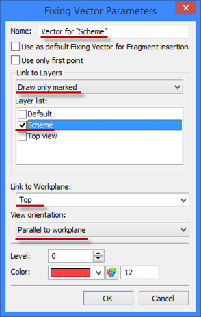
In the «Fixing vector parameters» window that appears we specify the name of the vector «Vector for “Scheme”». In the «Connection with layers» field we select the «Draw only marked items» option, so that upon rendering only the drawing located on the selected layer is displayed as a fragment. From the list of layers we select the «Scheme» layer. In the «Connection with workplane» field we select the plane with which the fixing vector will be linked. In the «View orientation» field we select the option of axial symmetry. The same sequence of actions should be repeated for the second drawing, by indicating another layer. Creation of fixing vectors is described in more detail in the «Ways of attaching fragments» section of the «2D–fragments – Bottom-Up Design» chapter. As a result we have two schemes for insertion into the assembly’s drawing. Projective connection must exist between the model and the scheme, i.e. schematic image must be located at the same place where the projection of the model would be located. In our example the schemes are created on the same page, that’s why before adding the model to the assembly the schemes must be combined (place the «Top view» drawing above the «Scheme» drawing). |

Save the file of the fragment.
Creating schematic image of 3D fragment in the assembly
Open the assembly’s file. It contains two connected elements of the pipeline. The elements of the schematic view were created for them in advance.

Go to the page of the «Top view» workplane.
For the pages of the workplanes to be displayed in 2D window, the command must be invoked
Icon |
Ribbon |
|---|---|
|
Edit → Document → Pages |
Keyboard |
Textual Menu |
<PG> |
Customize > Pages |
This command can be invoked only when 2D window is active. In the window that appears enable the «Workplane» flag. Now at the bottom of 2D window the tabs of the workplanes will be displayed. |
|
This command can be invoked only when 2D window is active. In the window that appears enable the «Workplane» flag. Now at the bottom of 2D window the tabs of the workplanes will be displayed.
Invoke the command
Icon |
Ribbon |
|---|---|
|
Assembly → Assembly → 3D Fragment |
Keyboard |
Textual Menu |
<3F> |
Operation > Insert 3D Fragment |
After the 3D fragment has been inserted into the assembly we invoke the command
Icon |
Ribbon |
|---|---|
|
Draw → Insert → Fixing Vector |
Keyboard |
Textual Menu |
<FR> |
Draw > Fragment |
Now we activate the automenu option
|
<W> |
Project 3D fragments onto a workplane |
We select the plane on which will be created the image and the body, for which this image will be created. There is a capability of selecting simultaneously several bodies manually or all bodies in the scene with the help of the option
|
<A> |
Select all 3D fragments in the scene |
For a current 3D fragment, the source for the 2D fragment being created can be selected from the list of the «Fixing» field:
●Vector projection – projection of the selected model based on its graphic lines is created;
●Raster projection – projection of the selected model as a 2D fragment is created;
●Fixing vector – schematic view created earlier is added to the plane. Only those vectors that satisfy the workplanes compatibility condition are added to the list.

We select «Vector for “Scheme”» and press «Finish input». On the «Top view» plane the new schematic image has been created.
3D fragment and schematic image will be synchronically moving in space. For example, when translating a 2D-fragment, the 3D fragment will also change its location. At the same time some degrees of freedom of a dragger can be automatically suppressed upon this translation (become grey), in order to prevent the break-up of connection with the schematic views on the other planes.

Fragment parameters
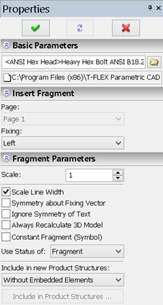
The section “Basic Parameters” contains data about the fragment file. The button ●..\..\folder\file_name.grb – in this case, the record is made relative to the file of the assembly drawing. The symbol ..\ denotes going along the folders by one level up with respect the assembly file. ●<library>file_name.grb – in this case, the reference uses the drawings library connected to T-FLEX CAD. It is recommended to use the relative references which operate in a more flexible way and are not tied to a specific place on the hard disk. It allows a user, for example, to move the assembly with all documents contained in it from one place to another without any losses. The section “Insert Fragment” allows a user to select the desired page of the document being inserted as a fragment (parameter “Page”). This parameter is not available if there is only one page in the fragment. Also, in the drop down list “Fixing” found in this section, the attachment approach is specified: either by fixing points or by fixing vector. |
|
The section “Fragment Parameters” contains different parameters of the fragment insertion:
Scale. Defines the scale of the fragment being inserted. This is used only when inserting fragments by fixing vectors.
Rotation Angle. Defines the angle of the fragment rotation. This is used only when inserting fragments by fixing vectors.
Scale line thickness. This parameter specifies whether to apply the assigned scale to the fragment lines thickness. This is used only when inserting fragments by fixing vectors.
Symmetry About Fixing Vector. When set, the fragment image will be mirrored about the fixing vector. This is used only when inserting fragments by fixing vectors.
Ignore text symmetry. This parameter is important when using the “Symmetry about vector” flag. When this parameter is enabled, texts on the fragment are not subjected to symmetric reflection with respect to the fixing vector (when the fragment itself is symmetric).
Always regenerate 3D model. With this flag set, the 3D model of the fragment will be automatically regenerated upon changes to the 2D fragment parameters.
Constant Fragment (Symbol). Setting this parameter makes the inserted fragment saved in the assembly document as a picture. This allows speeding up the work with the assembly since now there is no necessity to resort to external files. The fragment file is not read when opening the assembly. Owing to that, the fragment can be displayed in the assembly even in case its source file is absent. However, since this is a picture, other elements of the drawing cannot be fixed to it. Also, it is not possible to modify variables of such fragment from the variables editor of the assembly drawing (when the connection between the assembly variable and the fragment variable exists). Modifying variables is possible only upon editing such fragment on condition that the source file exists on the hard disk at the indicated reference.
Use Status of. As any T-FLEX drawing, the fragment has its own drawing settings defined in the commands "ST: Set Document Parameters" and "SH: Set Levels". Those include the line thickness, the font size, levels, etc. One of the two status settings can be selected for the fragment being inserted into the current drawing:
●Fragment. In this case, the fragment will be inserted with the settings defined in the fragment drawing.
●Current Document. The inserted fragment will adjust to the settings of the current document. This choice is used when the assembly drawing is required to maintain a uniform style. Besides, by changing the ranges of visibility levels you can "turn on" or "turn off" certain portions of the fragment drawing when it is used in an assembly. For instance, one can remove "extra" drawings or dimension symbols.
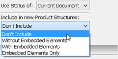
Include in Product Structures. This parameter manages incorporation of fragment data into the bill of materials of the current drawing. It can take the following values:
●Don’t Include - the fragment is not entered in the BOM table.
●Without Embedded Elements - the fragment is entered in the BOM table. If the fragment is an assembly itself, then only the fragment proprietary data is entered into the BOM. The information about the nested elements (lower-level fragments) is not included.
●With Embedded Elements - the fragment is entered into the BOM together with the nested elements.
●Embedded Elements Only - only the nested elements are entered into the BOM.

In this case, the name of the just described parameter will appear as "Include in new Product Strucuctures" and, therefore, this parameter will take effect only on the newly created product structure in the current document.
Additionally, a graphic button [Include in Product structure] will be provided for displaying the window with the list of product structures existing in the current document, and the settings of the fragment contribution to each of them.
By activating the «Specify workpiece’s structure name» option, one of the structures of the workpiece which are present in the fragment’s file can be selected. This option works only when the «with embedded elements» and «only embedded elements» parameters are enabled.

The way of including the given fragment into the assembly’s structure can also be specified with the help of the command:
Icon |
Ribbon |
|---|---|
|
Bill of materials → Product structure → Included fragments |
Keyboard |
Textual Menu |
<BI> |
Tools > Report/Bill of materials > Included fragments |
The section “Variables” allows a user to specify the values for the fragment external variables. This section is present in the command's properties window only if the fragment being inserted has external variables. Both the list of variables and the user-defined dialog of the fragment parameters (if it has been created in the document of the fragment being inserted) can be used for specifying external fragment variables. The choice of the desired way to work with the variables is made with the help of the flag “List of variables”. To make the work with user-defined dialogs more convenient, the section «Variables» in the command's properties window can be brought out as a separate window by pressing the button |
|
The section “Coordinates” can be used for specifying precise coordinate values for the points of the fixing vector or the fragment fixing points if these points are not being fixed to the elements of the drawing. The work with the fields in this section is similar to that described in the chapter “Sketch. Creating a Non-parametric Drawing. Automatic parameterization mode” of this manual. The structure of the controls in the section “Coordinates” changes depending on the situation: |
|
Section “Preview”. In this section of the properties window the diminished image of the fragment on the selected page is shown. The fixing vectors are also shown in this window if they exist. The desired fixing vector can be selected in this window by pointing at it. The selected fixing vector is shown with red color. The rest of the vectors are blue. Section “Options” contains the following parameters: Auto create 3D fragment. (Available only for 3D version). In case this flag is set on, right away after inserting the new 2D fragment the corresponding 3D fragment is automatically created with attachment by default (without using the coordinate system). Auto create. When turning on this flag, the process of inserting the fragment will be finished automatically straightway after specifying the fixing points or the points of the fixing vector of the fragment. Create internal fragment. This parameter allows a user to create an internal fragment, the contents of which are stored in the assembly drawing, but not in the external file. |
|
In the dialog of the fragment parameters (option ![]() ) the following parameters can be specified additionally:
) the following parameters can be specified additionally:
Priority. Defines the priority of the fragment in the assembly drawing. This is used for changing the order of drawing fragments within the current document and for the fragment hidden line removal. Priority is represented by an integer, positive or negative. Fragments with lower priority will be drawn in the screen prior to the fragments with higher priority. The priority of the current (assembly) drawing is equal to "0" by default.
Level. Sets the fragment level.
Layer. Sets the fragment layer.
The button "Options". Provides a shortcut to defining the system parameters for handling fragments. The parameters in this dialog are the same as those on the tab "Fragments" of the command "SO: Set System Options".