“Paper” Tab |
  
|
“Paper” Tab |
|

This tab defines main drawing parameters. The preview of the document layout with the specified parameters is available in the preview pane.
Paper size. This group of parameters defines the drawing boundaries.
Format. Provides selection from the list of main formats defined by common standards, such as ISO, ANSI, etc. If a standard format is selected then the “Width” and “Height” parameters are set automatically. If the “Custom” format is selected, then the sizes can be defined manually.
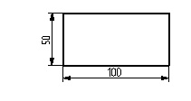
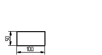
Width. Defines the format width size.
Height. Defines the format height size.
Orientation. This parameter defines the orientation of the drawing format. The orientation can be Portrait or Landscape.
Scale. Defines the drawing scale. An arbitrary value of the scale can be defined, or otherwise be selected from the list. It is recommended to use scale only when actually necessary. In most cases, scaling is not necessary for the following reasons:
1.When outputting to a plotter or printer, the drawing size is not a concern.
2.Special tools are provided for scaling dimension notations of the whole drawing or a portion thereof, as described below.
If it is still necessary to set a scale, it is better be done before starting creating the drawing. Changing the scale setting on an existing drawing may require manual editing of some of its elements. This is because scaling does not merely a proportional modification of all drawing element sizes. The scale in T-FLEX defines only the drawing lines locations, while, for instance, the size of dimension arrows and text will stay unchanged.
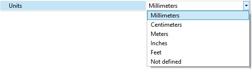
Units. Defines the measurement units used by T-FLEX CAD. This parameter is selected from the list.
This parameter affects several issues, such as the following:
-Calculating dimension tolerances that is done differently in metric and inches systems;
-The menu settings when defining roughness parameters and GD&T symbols for surfaces;
-Output to a plotter;
-Exporting different formats;
-The way of converting dimension values, if a conversion system is assigned on the Dimensions tab in groups Scale or Alternative scale to the Scale parameter.
Origin. The following parameters define the location of the origin of the drawing coordinate system.
X. Defines the X coordinate of the drawing lower-left corner.
Y. Defines the Y coordinate of the drawing lower-left corner.
The coordinate values are defined in the same units as used for creating the drawing. These are defined under the “Units” item.
When defining document parameters, one can use variables that will be stored in the drawing file. To do so, enter a variable name instead of a particular parameter value, whether numerical or string. The variable name must be entered in {braces}. If it is a string variable, its name must begin with “$” character. Pressing <F8> while in the intended input box allows selecting the variable from the list of already created ones. The variable values can be modified using the variable editor.