Element Layers. Selecting element layer. Creating layers and setting their parameters |
  
|
Element Layers. Selecting element layer. Creating layers and setting their parameters |
|
A layer is a parameter of any drawing element. It defines the element association with a particular group of the model elements.
The user can define the layer name for each system element to belong to. A layer name is a string of up to 20 text characters. An element layer can also be set on the system toolbar.
![]()
Layer parameters can be created, deleted and modified using the command "QL: Configure Layers":
Icon |
Ribbon |
|---|---|
|
Edit → Document → Layers |
Keyboard |
Textual Menu |
<QL> |
Customize > Layers |
After calling this command the dialog window “Layers” appears. In the window of the given dialog box the list of the layers existing in the given document and their parameters are shown. Under this list there are fields for assigning parameters of the layer and buttons for performing different actions with the fields.
The button [New] creates the new layer in the document. After pressing this button the system asks to give a name to the created layer.
The button [Delete] removes unused layer (it becomes available only upon selecting from the list the layer marked with the sign ![]() ). The button [Rename] allows assigning the new name for the layer selected from the layers list.
). The button [Rename] allows assigning the new name for the layer selected from the layers list.
The buttons [Sort], [Up], [Down] are used for changing the arrangement of the layers in the list. The layers arrangement is enforced in all dialog boxes of the system which allow selection of the layer.
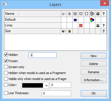
For changing parameters of any layer it is necessary to select it from the list of the layers and set on/off the required flags under the list. By entering layer parameters you define the properties of the elements belonging to this layer. The following parameters can be defined for each layer:
Hidden. A layer can also be assigned invisible property by using a variable. The variable can have two values: 0 – the layer is visible, and 1 – the layer is invisible.
The variable values different from 0 and 1, are processed by the system as follows: the fractional part is dropped, and the resulting number is matched with 0. If matching, the layer will be visible, otherwise – invisible.
Frozen. When set, no element on this layer will be allowed for selection during element creation and editing.
Screen only. When set, all elements on this layer will be displayed on the screen only, but will not be printed, plotted or exported.
Hidden when model is used as a Fragment. When set, the elements on this layer will not be displayed when the drawing is used as a fragment.
Visible only when model is used as a Fragment. When set, the elements on this layer will only be displayed when the drawing is used as a fragment of an assembly.
Color. When set, all elements on this layer will be displayed in the specified color after the redraw. The color is selected from the color menu.
Line thickness. Upon enabling this flag, the same thickness will be set for all graphic lines in the given layer.